Product Description
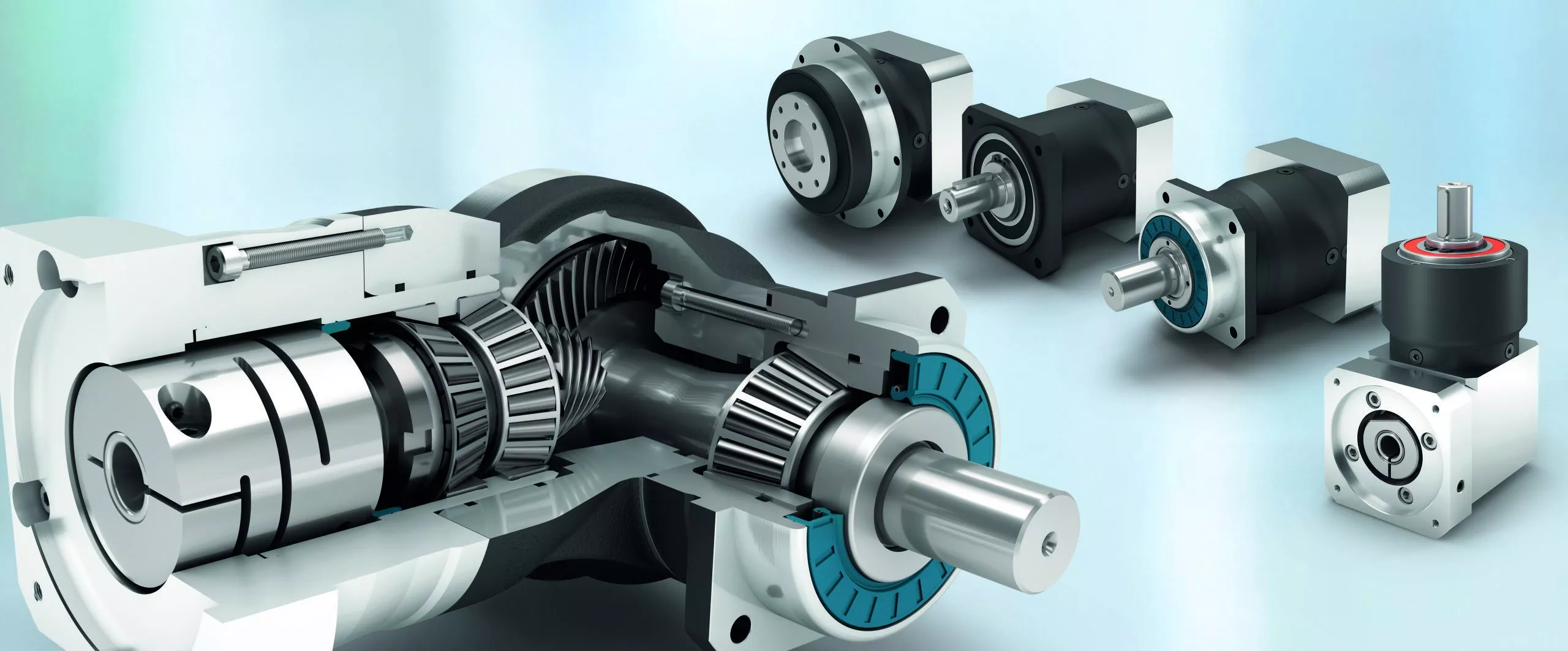
Precision planetary gear reducer is a new-generation of product developed by our company, with a compromise of advanced technology both at home and abroad, its main features are as follows:
1. Low noise: under 65db.
2. Low backlash: within 3 arcmin.
3. High efficiency: 97% for 1 stage, 94% for 2 stages.
4. High input speed: Rated input speed 3000rpm, max input speed 6000 rpm.
5. High output torque: higher torque output than that of conventional planetary gear reducer.
6. High stability hardening,which extends gear service life and maintain high accuracy as new after a long period of operation.
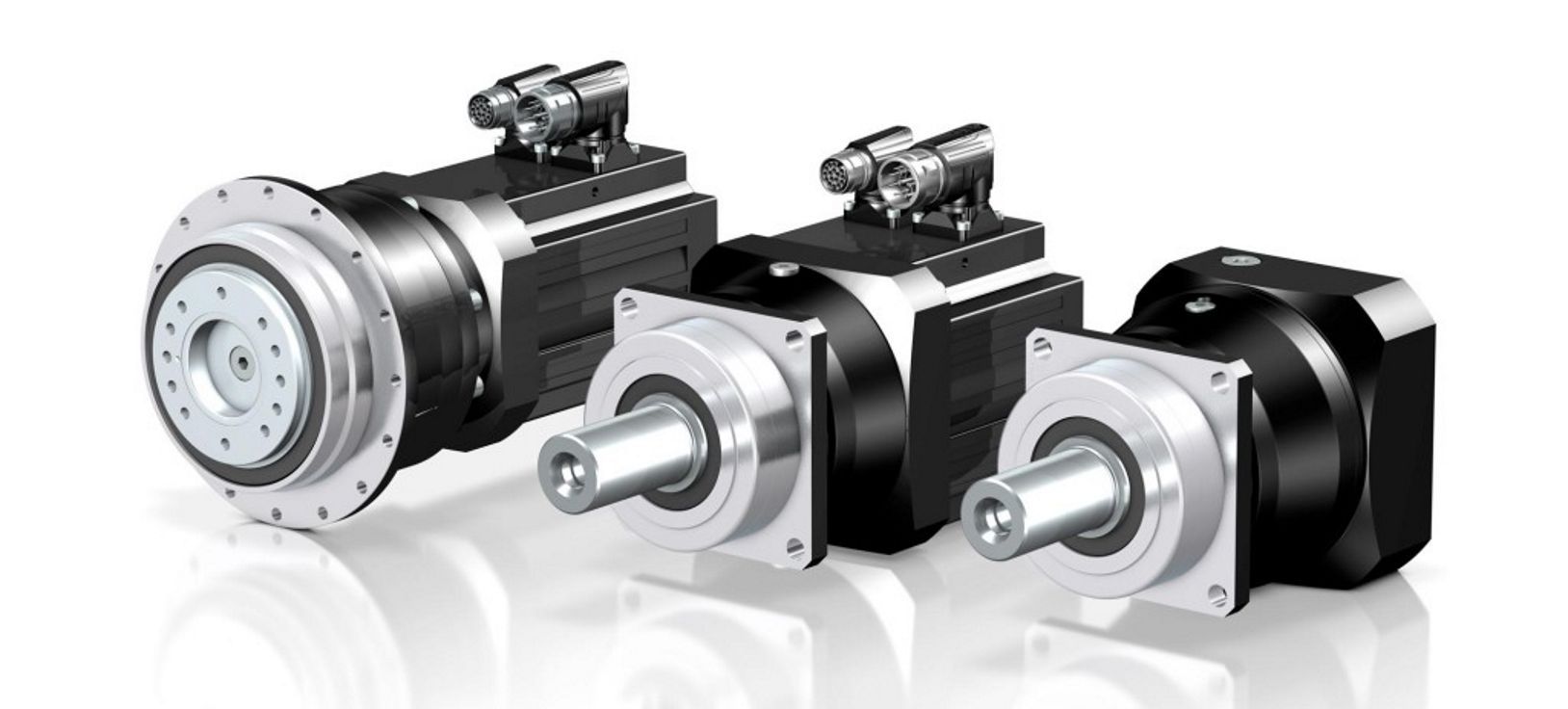
Precicion planetary gear reducer is widely used in the following fields:
1. Aerospace industries.
2. Medical health, electronic information industries.
3. Industrial robots, productin automation, CNC machine tool manufacturing industries.
4. Motor,textile,printing,food,metallurgical,envrironment protection engineering, warehouse logistics industries.
About Xingda since 1984
HangZhou Melchizedek Import & Export Co., Ltd. is a leader manufactur in mechanism field and punching/stamp
ing field since 1984. Our main product, NMRV worm gear speed reducer and series helical gearbox, XDR,
XDF, XDK, XDShave reached the advanced technique index of the congeneric European and Janpanese produc
ts, We offer standard gears, sprockets, chains, pulleys, couplings, bushes and so on. We also can accept orders
of non-standard products, such as gears, shafts, punching parts ect, according to customers’ Drawings or sam-
ples.
Our company has complete set of equipment including CNC, lathes, milling machines, gear hobbing machine, g-
ear grinding machine, gear honing machine, gear shaping machine, worm grinder, grinding machines, drilling m-
achines, boringmachines, planer, drawing benches, punches, hydraulic presses, plate shearing machines and s-
o on. We have advanced testing equipments also.
Our company has established favorable cooperation relationships with sub-suppliers involving casting, raw mat-
erial, heat treatment, surface finishing and so on.
| Application: | Motor, Machinery |
|---|---|
| Hardness: | Hardened Tooth Surface |
| Installation: | Vertical Type |
| Gear Shape: | Helical |
| Step: | Single-Step |
| Type: | Planetary Gear Reducer |
| Samples: |

Real-World Examples of Products Using Servo GearboxesServo gearboxes find application in various industries and products, contributing to their precision, efficiency, and performance:
These examples demonstrate the widespread adoption of servo gearboxes across various industries, where precision, accuracy, and controlled motion are critical for efficient and high-performance operations.
US$ 230/Piece
1 Piece(Min.Order) | |
|---|
| Customization: |
Available
| Customized Request |
|---|
Benefits of Using a Servo Gearbox for Precise Motion Control
Servo gearboxes offer several advantages when it comes to achieving precise motion control in various applications:
1. Accuracy: Servo gearboxes provide exceptional accuracy in speed and position control, making them suitable for applications that require tight tolerances and precise movements.
2. Low Backlash: These gearboxes are designed to minimize backlash, which is essential for eliminating lost motion and ensuring accurate positioning.
3. High Torque Density: Servo gearboxes offer a high torque-to-size ratio, allowing them to handle significant loads while maintaining a compact footprint.
4. Dynamic Performance: They excel in dynamic performance, enabling rapid changes in speed and direction with minimal overshoot or settling time.
5. Responsiveness: Servo gearboxes respond quickly to control signals, making them ideal for applications that require rapid adjustments and changes in direction.
6. Smooth Operation: These gearboxes provide smooth and precise movement, critical for applications like robotics, where jerky or uneven motion can lead to inaccuracies or damage.
7. Reduces Maintenance: The accuracy and durability of servo gearboxes can reduce wear and tear on other components, leading to lower maintenance requirements.
8. Improved Efficiency: Servo gearboxes offer high efficiency in power transmission, contributing to energy savings and minimizing heat generation.
9. Customization: They can be tailored to specific application needs, including factors like reduction ratios, mounting options, and feedback compatibility.
10. Versatility: Servo gearboxes find application in various industries, including robotics, CNC machining, medical equipment, and automation.
Overall, the benefits of using a servo gearbox for precise motion control make them an essential component in applications that demand accuracy, responsiveness, and reliable performance.


editor by CX 2023-08-14
China wholesaler High Precision Low Backlash Speed Reduction Stepper Motor Servo Motor Planetary Gearbox wholesaler
Product Description
Product Description
HPS is a leading manufacturer and supplier of planetary gearbox and gear motor in China, Our company covers an area of 6 pcs. Meanwhile, all 6 production lines strictly comply with ISO 9001 and CE to control the quality. wide-range series products have been exported to 30+ countries all over the world.
Besides, we are making great efforts to customize and provide complete solutions to meet different clients’ requirements and market. Our R&D team has 15 years experience in this field, makes our company honored with many invention patents and utility patents, which makes CZPT the most trustable and reliable manufacturer.
| SPECIFICATIONS | STAGE | RATIO | RATED TORQUE (N.m) | ||
| PLE42-L2SW Planetry Gearbox | L2 | 16 | 12 | ||
| 20 | 12 | ||||
| 25 | 12 | ||||
| 28 | 12 | ||||
| 35 | 10 | ||||
| 40 | 10 | ||||
| 50 | 10 | ||||
| 70 | 10 | ||||
| 100 | 10 | ||||
| Adapted motor | ∅5-24/ ∅22-2/F31-M3 | ||||
| Rated Input Speed (rpm) | 3000 | ||||
| Max Input Speed (rpm) | 6000 | ||||
| Backlash | L2 | ≤15 Arcmin | |||
| Fault stop torque(N.m) | 2 times of rated torque | ||||
| Efficiency | L2 | 96% | |||
| Average life span | 20000h | ||||
| Operating temperature | -10°~+90° | ||||
| Nosie | ≤55 db | ||||
| IP | 54 | ||||
| Installation method | Any installation method | ||||
Production & Test Equipments
Exhibition
HPS attends 5-6 exhibitions every year, both solar PV exhibitions and automation industry exhibitions, professional sales team and quality products build CZPT a good reputation in the market.
Certificates
Successful Projects
Packaging & Shipping
FAQ
Q1:Which areas are your products mainly used in?
A:At present, we have 2 main products: precision planetary gear reducer and solar geared motor. Most of the precision planetary reducers are used in automation fields, such as medical equipment, 3D printers, door openers, tapping machines, CNC lathes and a series of automation equipment. In addition, our solar geared motors are used in photovoltaic power generation projects, which are mainly combined with rotary drives to drive solar panels to track sunlight.
Q2: How to choose the suitable planetary gearbox?
A :First of all, we need you to be able to provide relevant parameters. If you have a motor drawing, it will let us recommend a suitable gearbox for you faster. If not, we hope you can provide the following motor parameters: output speed, output torque, voltage, current, IP, noise, operating conditions, motor size and power, etc.
Q3: What is the price ?
A : The main determining factor for the price of each product is the order volume. You can communicate with us and let us understand each other. I believe that our prices, product quality and our services can definitely make you satisfied.
Q4: Do you provide customized service?
A: Yes, we provide customized services. You only need to put CZPT your needs, and we will do our best to provide you with a plan, make plans, and try our best to meet your needs.
| Application: | Motor, Machinery, Marine, Agricultural Machinery |
|---|---|
| Function: | Change Drive Torque, Speed Changing, Speed Reduction |
| Layout: | Coaxial |
| Hardness: | Hardened Tooth Surface |
| Installation: | Any Type |
| Step: | Double-Step |
| Samples: |
US$ 45/Piece
1 Piece(Min.Order) | |
|---|
| Customization: |
Available
| Customized Request |
|---|
Servo Gearboxes vs. Standard Gearboxes in Industrial Applications
Servo gearboxes and standard gearboxes serve distinct roles in industrial applications. Here’s how they differ:
Precision Control: Servo gearboxes are specifically designed for precise motion control in applications that require accurate speed and position control. Standard gearboxes, while also providing speed reduction or torque multiplication, may not offer the same level of precision.
Backlash: Servo gearboxes are designed to minimize backlash, which is crucial for applications where even slight lost motion is unacceptable. Standard gearboxes may have higher levels of backlash due to their broader design scope.
Dynamic Response: Servo gearboxes excel in dynamic response, enabling quick changes in speed and direction with minimal overshoot. Standard gearboxes may not offer the same level of responsiveness.
High Efficiency: Servo gearboxes are optimized for efficiency to ensure precise power transmission. Standard gearboxes may prioritize other factors like cost or load capacity.
Positioning Accuracy: Servo gearboxes are essential for achieving high positioning accuracy in applications such as robotics and CNC machines. Standard gearboxes might not meet the same accuracy requirements.
Load Distribution: Servo gearboxes distribute loads evenly across gear teeth to enhance durability and minimize wear. Standard gearboxes might not have the same load distribution capabilities.
Compact Design: Servo gearboxes are often designed with a compact form factor to fit within tight spaces. Standard gearboxes might be larger and less optimized for space constraints.
Customization: Servo gearboxes can be highly customizable in terms of size, reduction ratio, and mounting options. Standard gearboxes may offer fewer customization choices.
Application Focus: Servo gearboxes are intended for applications that demand precision and responsiveness, such as robotics, automation, and CNC machining. Standard gearboxes are used in a broader range of applications where precision might not be as critical.
In summary, servo gearboxes are specialized components tailored for high-precision motion control applications, while standard gearboxes serve a wider variety of industrial needs with a focus on durability, load handling, and basic speed reduction.
editor by CX 2023-08-14
China wholesaler n20 mini dc motor plastic planetary gearbox 6v for lock straight bevel gear
Warranty: Other
Model Number: 12GR120-N20VA
Usage: Electric Bicycle, Home Appliance, Electronic door lock ,safe box, high power mining gearbox gallery industry reducer rolling mill industrial gear motor for cement industry toy
Type: GEAR MOTOR
Torque: 250g.cm
Construction: Permanent Magnet
Commutation: Brush
Protect Feature: Totally Enclosed
Speed(RPM): 120rpm
Continuous Current(A): 90mA
Efficiency: IE 1
Diversion: CW
Gears: Gearbox Reducer
Gear Type: Plantary Gearbox
Diameter: 12mm
Keywords: N20 Gear Motor
Brush: Precision Metal
Certification: ce, RoHS, ISO9 Ring Gear & Pinion set suitable for CZPT TL TL90A TD90A TD95A JX80 JX90 JX95 and long-term customization
Production Process
Our Services Customization service as below are available
Packaging & Shipping
FAQ
Q: Are you trading company or manufacturer ?A: We are factory.
Q: How long is your delivery time?A: Generally it is 5-10 days if the goods are in stock. or it is 20-30 days if the goods are not in stock, it is according to quantity.
Q: Do you provide samples ? is it free or extra ?A: The sample fee is according to the stock and cost.
Q: What is your terms of payment ?A: Payment=1000USD, 30% T/T in advance , Industrial Fruit Vegetable And Flower Dehydrator Dryer Machine balance before shippment.
Hypoid Bevel Vs Straight Spiral Bevel – What’s the Difference?
Spiral gears come in many different varieties, but there is a fundamental difference between a Hypoid bevel gear and a Straight spiral bevel. This article will describe the differences between the two types of gears and discuss their use. Whether the gears are used in industrial applications or at home, it is vital to understand what each type does and why it is important. Ultimately, your final product will depend on these differences.
Hypoid bevel gears
In automotive use, hypoid bevel gears are used in the differential, which allows the wheels to rotate at different speeds while maintaining the vehicle’s handling. This gearbox assembly consists of a ring gear and pinion mounted on a carrier with other bevel gears. These gears are also widely used in heavy equipment, auxiliary units, and the aviation industry. Listed below are some common applications of hypoid bevel gears.
For automotive applications, hypoid gears are commonly used in rear axles, especially on large trucks. Their distinctive shape allows the driveshaft to be located deeper in the vehicle, thus lowering the center of gravity and minimizing interior disruption. This design makes the hypoid gearset one of the most efficient types of gearboxes on the market. In addition to their superior efficiency, hypoid gears are very easy to maintain, as their mesh is based on sliding action.
The face-hobbed hypoid gears have a characteristic epicycloidal lead curve along their lengthwise axis. The most common grinding method for hypoid gears is the Semi-Completing process, which uses a cup-shaped grinding wheel to replace the lead curve with a circular arc. However, this method has a significant drawback – it produces non-uniform stock removal. Furthermore, the grinding wheel cannot finish all the surface of the tooth.
The advantages of a hypoid gear over a spiral bevel gear include a higher contact ratio and a higher transmission torque. These gears are primarily used in automobile drive systems, where the ratio of a single pair of hypoid gears is the highest. The hypoid gear can be heat-treated to increase durability and reduce friction, making it an ideal choice for applications where speed and efficiency are critical.
The same technique used in spiral bevel gears can also be used for hypoid bevel gears. This machining technique involves two-cut roughing followed by one-cut finishing. The pitch diameter of hypoid gears is up to 2500 mm. It is possible to combine the roughing and finishing operations using the same cutter, but the two-cut machining process is recommended for hypoid gears.
The advantages of hypoid gearing over spiral bevel gears are primarily based on precision. Using a hypoid gear with only three arc minutes of backlash is more efficient than a spiral bevel gear that requires six arc minutes of backlash. This makes hypoid gears a more viable choice in the motion control market. However, some people may argue that hypoid gears are not practical for automobile assemblies.
Hypoid gears have a unique shape – a cone that has teeth that are not parallel. Their pitch surface consists of two surfaces – a conical surface and a line-contacting surface of revolution. An inscribed cone is a common substitute for the line-contact surface of hypoid bevel gears, and it features point-contacts instead of lines. Developed in the early 1920s, hypoid bevel gears are still used in heavy truck drive trains. As they grow in popularity, they are also seeing increasing use in the industrial power transmission and motion control industries.
Straight spiral bevel gears
There are many differences between spiral bevel gears and the traditional, non-spiral types. Spiral bevel gears are always crowned and never conjugated, which limits the distribution of contact stress. The helical shape of the bevel gear is also a factor of design, as is its length. The helical shape has a large number of advantages, however. Listed below are a few of them.
Spiral bevel gears are generally available in pitches ranging from 1.5 to 2500 mm. They are highly efficient and are also available in a wide range of tooth and module combinations. Spiral bevel gears are extremely accurate and durable, and have low helix angles. These properties make them excellent for precision applications. However, some gears are not suitable for all applications. Therefore, you should consider the type of bevel gear you need before purchasing.
Compared to helical gears, straight bevel gears are easier to manufacture. The earliest method used to manufacture these gears was the use of a planer with an indexing head. However, with the development of modern manufacturing processes such as the Revacycle and Coniflex systems, manufacturers have been able to produce these gears more efficiently. Some of these gears are used in windup alarm clocks, washing machines, and screwdrivers. However, they are particularly noisy and are not suitable for automobile use.
A straight bevel gear is the most common type of bevel gear, while a spiral bevel gear has concave teeth. This curved design produces a greater amount of torque and axial thrust than a straight bevel gear. Straight teeth can increase the risk of breaking and overheating equipment and are more prone to breakage. Spiral bevel gears are also more durable and last longer than helical gears.
Spiral and hypoid bevel gears are used for applications with high peripheral speeds and require very low friction. They are recommended for applications where noise levels are essential. Hypoid gears are suitable for applications where they can transmit high torque, although the helical-spiral design is less effective for braking. For this reason, spiral bevel gears and hypoids are generally more expensive. If you are planning to buy a new gear, it is important to know which one will be suitable for the application.
Spiral bevel gears are more expensive than standard bevel gears, and their design is more complex than that of the spiral bevel gear. However, they have the advantage of being simpler to manufacture and are less likely to produce excessive noise and vibration. They also have less teeth to grind, which means that they are not as noisy as the spiral bevel gears. The main benefit of this design is their simplicity, as they can be produced in pairs, which saves money and time.
In most applications, spiral bevel gears have advantages over their straight counterparts. They provide more evenly distributed tooth loads and carry more load without surface fatigue. The spiral angle of the teeth also affects thrust loading. It is possible to make a straight spiral bevel gear with two helical axes, but the difference is the amount of thrust that is applied to each individual tooth. In addition to being stronger, the spiral angle provides the same efficiency as the straight spiral gear.
Hypoid gears
The primary application of hypoid gearboxes is in the automotive industry. They are typically found on the rear axles of passenger cars. The name is derived from the left-hand spiral angle of the pinion and the right-hand spiral angle of the crown. Hypoid gears also benefit from an offset center of gravity, which reduces the interior space of cars. Hypoid gears are also used in heavy trucks and buses, where they can improve fuel efficiency.
The hypoid and spiral bevel gears can be produced by face-hobbing, a process that produces highly accurate and smooth-surfaced parts. This process enables precise flank surfaces and pre-designed ease-off topographies. These processes also enhance the mechanical resistance of the gears by 15 to 20%. Additionally, they can reduce noise and improve mechanical efficiency. In commercial applications, hypoid gears are ideal for ensuring quiet operation.
Conjugated design enables the production of hypoid gearsets with length or profile crowning. Its characteristic makes the gearset insensitive to inaccuracies in the gear housing and load deflections. In addition, crowning allows the manufacturer to adjust the operating displacements to achieve the desired results. These advantages make hypoid gear sets a desirable option for many industries. So, what are the advantages of hypoid gears in spiral gears?
The design of a hypoid gear is similar to that of a conventional bevel gear. Its pitch surfaces are hyperbolic, rather than conical, and the teeth are helical. This configuration also allows the pinion to be larger than an equivalent bevel pinion. The overall design of the hypoid gear allows for large diameter shafts and a large pinion. It can be considered a cross between a bevel gear and a worm drive.
In passenger vehicles, hypoid gears are almost universal. Their smoother operation, increased pinion strength, and reduced weight make them a desirable choice for many vehicle applications. And, a lower vehicle body also lowers the vehicle’s body. These advantages made all major car manufacturers convert to hypoid drive axles. It is worth noting that they are less efficient than their bevel gear counterparts.
The most basic design characteristic of a hypoid gear is that it carries out line contact in the entire area of engagement. In other words, if a pinion and a ring gear rotate with an angular increment, line contact is maintained throughout their entire engagement area. The resulting transmission ratio is equal to the angular increments of the pinion and ring gear. Therefore, hypoid gears are also known as helical gears.


China wholesaler K series spiral bevel gear reducerSpeed reducerSmall speed reducer gearbox bevel spiral gear
Warranty: 1 year
Applicable Industries: Building Material Shops, Manufacturing Plant, Machinery Repair Shops, Food & Beverage Factory, Printing Shops, Construction works , Energy & Mining, Food & Beverage Shops
Weight (KG): 55 KG
Gearing Arrangement: Helical
Output Torque: 105 (WhatsApp & Wechat)
Synthesis of Epicyclic Gear Trains for Automotive Automatic Transmissions
In this article, we will discuss the synthesis of epicyclic gear trains for automotive automatic transmissions, their applications, and cost. After you have finished reading, you may want to do some research on the technology yourself. Here are some links to further reading on this topic. They also include an application in hybrid vehicle transmissions. Let’s look at the basic concepts of epicyclic gear trains. They are highly efficient and are a promising alternative to conventional gearing systems.
Synthesis of epicyclic gear trains for automotive automatic transmissions
The main purpose of automotive automatic transmissions is to maintain engine-drive wheel balance. The kinematic structure of epicyclic gear trains (EGTs) is derived from graph representations of these gear trains. The synthesis process is based on an algorithm that generates admissible epicyclic gear trains with up to ten links. This algorithm enables designers to design auto gear trains that have higher performance and better engine-drive wheel balance.
In this paper, we present a MATLAB optimization technique for determining the gear ratios of epicyclic transmission mechanisms. We also enumerate the number of teeth for all gears. Then, we estimate the overall velocity ratios of the obtained EGTs. Then, we analyze the feasibility of the proposed epicyclic gear trains for automotive automatic transmissions by comparing their structural characteristics.
A six-link epicyclic gear train is depicted in the following functional diagram. Each link is represented by a double-bicolor graph. The numbers on the graph represent the corresponding links. Each link has multiple joints. This makes it possible for a user to generate different configurations for each EGT. The numbers on the different graphs have different meanings, and the same applies to the double-bicolor figure.
In the next chapter of this article, we discuss the synthesis of epicyclic gear trains for automotive automatic transaxles. SAE International is an international organization of engineers and technical experts with core competencies in aerospace and automotive. Its charitable arm, the SAE Foundation, supports many programs and initiatives. These include the Collegiate Design Series and A World In Motion(r) and the SAE Foundation’s A World in Motion(r) award.
Applications
The epicyclic gear system is a type of planetary gear train. It can achieve a great speed reduction in a small space. In cars, epicyclic gear trains are often used for the automatic transmission. These gear trains are also useful in hoists and pulley blocks. They have many applications in both mechanical and electrical engineering. They can be used for high-speed transmission and require less space than other types of gear trains.
The advantages of an epicyclic gear train include its compact structure, low weight, and high power density. However, they are not without disadvantages. Gear losses in epicyclic gear trains are a result of friction between gear tooth surfaces, churning of lubricating oil, and the friction between shaft support bearings and sprockets. This loss of power is called latent power, and previous research has demonstrated that this loss is tremendous.
The epicyclic gear train is commonly used for high-speed transmissions, but it also has a small footprint and is suitable for a variety of applications. It is used as differential gears in speed frames, to drive bobbins, and for the Roper positive let-off in looms. In addition, it is easy to fabricate, making it an excellent choice for a variety of industrial settings.
Another example of an epicyclic gear train is the planetary gear train. It consists of two gears with a ring in the middle and the sun gear in the outer ring. Each gear is mounted so that its center rotates around the ring of the other gear. The planet gear and sun gear are designed so that their pitch circles do not slip and are in sync. The planet gear has a point on the pitch circle that traces the epicycloid curve.
This gear system also offers a lower MTTR than other types of planetary gears. The main disadvantage of these gear sets is the large number of bearings they need to run. Moreover, planetary gears are more maintenance-intensive than parallel shaft gears. This makes them more difficult to monitor and repair. The MTTR is also lower compared to parallel shaft gears. They can also be a little off on their axis, causing them to misalign or lose their efficiency.
Another example of an epicyclic gear train is the differential gear box of an automobile. These gears are used in wrist watches, lathe machines, and automotives to transmit power. In addition, they are used in many other applications, including in aircrafts. They are quiet and durable, making them an excellent choice for many applications. They are used in transmission, textile machines, and even aerospace. A pitch point is the path between two teeth in a gear set. The axial pitch of one gear can be increased by increasing its base circle.
An epicyclic gear is also known as an involute gear. The number of teeth in each gear determines its rate of rotation. A 24-tooth sun gear produces an N-tooth planet gear with a ratio of 3/2. A 24-tooth sun gear equals a -3/2 planet gear ratio. Consequently, the epicyclic gear system provides high torque for driving wheels. However, this gear train is not widely used in vehicles.
Cost
The cost of epicyclic gearing is lower when they are tooled rather than manufactured on a normal N/C milling machine. The epicyclic carriers should be manufactured in a casting and tooled using a single-purpose machine that has multiple cutters to cut the material simultaneously. This approach is widely used for industrial applications and is particularly useful in the automotive sector. The benefits of a well-made epicyclic gear transmission are numerous.
An example of this is the planetary arrangement where the planets orbit the sun while rotating on its shaft. The resulting speed of each gear depends on the number of teeth and the speed of the carrier. Epicyclic gears can be tricky to calculate relative speeds, as they must figure out the relative speed of the sun and the planet. The fixed sun is not at zero RPM at mesh, so the relative speed must be calculated.
In order to determine the mesh power transmission, epicyclic gears must be designed to be able to “float.” If the tangential load is too low, there will be less load sharing. An epicyclic gear must be able to allow “float.” It should also allow for some tangential load and pitch-line velocities. The higher these factors, the more efficient the gear set will be.
An epicyclic gear train consists of two or more spur gears placed circumferentially. These gears are arranged so that the planet gear rolls inside the pitch circle of the fixed outer gear ring. This curve is called a hypocycloid. An epicyclic gear train with a planet engaging a sun gear is called a planetary gear train. The sun gear is fixed, while the planet gear is driven.
An epicyclic gear train contains several meshes. Each gear has a different number of meshes, which translates into RPM. The epicyclic gear can increase the load application frequency by translating input torque into the meshes. The epicyclic gear train consists of 3 gears, the sun, planet, and ring. The sun gear is the center gear, while the planets orbit the sun. The ring gear has several teeth, which increases the gear speed.
Another type of epicyclic gear is the planetary gearbox. This gear box has multiple toothed wheels rotating around a central shaft. Its low-profile design makes it a popular choice for space-constrained applications. This gearbox type is used in automatic transmissions. In addition, it is used for many industrial uses involving electric gear motors. The type of gearbox you use will depend on the speed and torque of the input and output shafts.
China Professional high torque planetary reducer nema 34 high precision planetary gearbox with Great quality
Applicable Industries: Building Material Shops, Manufacturing Plant, Machinery Repair Shops, Food & Beverage Factory, Farms, Home Use, Retail, Printing Shops, Construction works , Energy & Mining, Advertising Company
Gearing Arrangement: Planetary
Output Torque: 18-19000N.m
Input Speed: 1500-3000rpm
Output Speed: 1.5-1000rpm(customized)
Product name: feco
Application: automobile assembly
Ratio: 3-1000
Material of Housing: Metal
Type: for servo motor
Certificate: ISO9001
Mounting Position: Vertical (flange Mounted)
Warranty: 18 months
Heat treatment: Gear Grinding
Color: Customer Requirement
Packaging Details: Inside:carton boxes Outside:wooden cases
Port: ZheJiang
high precision and high torque nema 34 2 speed planetary gearbox
| Planetary Gearbox | |
| Efficiency | > High Torque Planetary Gearbox Mixer Drive Unit Harmonic Reducer For Concrete Mixer OEM T 90 Degree Gearbox =97% |
| Housing material | SCM415 |
| Gear material | SCM415 |
| Surface hardness of gears | 60±2HRC |
| Input / Output shaft material | SCM415 |
| Machining precision of gears | DIN6 Grade |
| Lubricating oil | KLUBER |
| Heat treatment | Carburizing, carbonitriding, brilliant quenching |
| Brand of bearings | NSK/NTN |
| Brand of oil seal | SKF/TTO |
| Noise (MAX) | 60-70dB |
| Temp. rise (MAX) | 70℃ |
| Oil Temp. rise (MAX) | 40℃ |
| Vibration | ≤15μm |
Main Features:
High precision:Adopt Japanese CZPT and HAMAYI advanced equipment.Quality and technology are strictly controlled.
High torque:(1)Front shell and tooth ring adopt integral design(2)Integrated design of planetary frame and output shaft(3)Bearing long span design, High Temperature Resistance NMRV Series 9-4 Copper Worm High Efficiency Durable Worm Gear Speed Reducer ensure the output load capacity(4) Full needle rolling, increase contact surface, increase output torque(5)Input flange interchangeability, ensure the exchange cycle(6) Modular design of motor connection plate and axle liner
Low noise:The helical tooth surface is modified for tooth shape and leadReduce the impact and noise of gear on the input and outputIncrease gear service life
Long life:NSK/NTN bearing:Steel: Japan steel (SCM415)Grease: KLUBEROil seal: SKF/TTO
Structure diagram:
Production Equipment high precision and high torque nema 34 2 speed planetary gearbox
Checkout Equipment Exhibition Our Company high precision and high torque nema 34 2 speed planetary gearbox
Related Products CH AC gear motor91.8% Response Rate
CV AC gear motor91.8% Response Rate
NMRV worm gearbox91.8% Response Rate
Packing & Delivery
| Packaging | |
| Size | Actual cargo size |
| Weight | Actual cargo size |
| Packaging Details | The normal package is wooden box(Size: L*W*H). If export to european countries,the wooden box will be fumigated.If container is too tigher,we will use pe film for packing or pack it according to customers special request. |
FAQ1. How to choose a gearbox which meets our requirement?You can refer to our catalogue to choose the gearbox or we can help to choose when you providethe technical information of required output torque, output speed and motor parameter etc.2. What information shall we give before placing a purchase order?a) Type of the gearbox, high precision planetary gearbox with servo motor ratio, input and output type, input flange, mounting position, and motor informationetc.b) Housing color.c) Purchase quantity.d) Other special requirements.3. What industries are your gearboxes being used?Our gearboxes are widely used in the areas of textile, food processing, beverage, chemical industry,escalator,automatic storage equipment, metallurgy, High quality S seties worm gear motor for sale mechanical lift worm gear screw jack design electric motor reduction gearbox tabacco, environmental protection, logistics and etc.4. Do you sell motors?We have stable motor suppliers who have been coperating with us for a long-time. They can provide motorswith high quality.
Contact us New blueprint new base.We wish to established common development with customers worldwide.
Spiral Gears for Right-Angle Right-Hand Drives
Spiral gears are used in mechanical systems to transmit torque. The bevel gear is a particular type of spiral gear. It is made up of two gears that mesh with one another. Both gears are connected by a bearing. The two gears must be in mesh alignment so that the negative thrust will push them together. If axial play occurs in the bearing, the mesh will have no backlash. Moreover, the design of the spiral gear is based on geometrical tooth forms.
Equations for spiral gear
The theory of divergence requires that the pitch cone radii of the pinion and gear be skewed in different directions. This is done by increasing the slope of the convex surface of the gear’s tooth and decreasing the slope of the concave surface of the pinion’s tooth. The pinion is a ring-shaped wheel with a central bore and a plurality of transverse axes that are offset from the axis of the spiral teeth.
Spiral bevel gears have a helical tooth flank. The spiral is consistent with the cutter curve. The spiral angle b is equal to the pitch cone’s genatrix element. The mean spiral angle bm is the angle between the genatrix element and the tooth flank. The equations in Table 2 are specific for the Spread Blade and Single Side gears from Gleason.
The tooth flank equation of a logarithmic spiral bevel gear is derived using the formation mechanism of the tooth flanks. The tangential contact force and the normal pressure angle of the logarithmic spiral bevel gear were found to be about twenty degrees and 35 degrees respectively. These two types of motion equations were used to solve the problems that arise in determining the transmission stationary. While the theory of logarithmic spiral bevel gear meshing is still in its infancy, it does provide a good starting point for understanding how it works.
This geometry has many different solutions. However, the main two are defined by the root angle of the gear and pinion and the diameter of the spiral gear. The latter is a difficult one to constrain. A 3D sketch of a bevel gear tooth is used as a reference. The radii of the tooth space profile are defined by end point constraints placed on the bottom corners of the tooth space. Then, the radii of the gear tooth are determined by the angle.
The cone distance Am of a spiral gear is also known as the tooth geometry. The cone distance should correlate with the various sections of the cutter path. The cone distance range Am must be able to correlate with the pressure angle of the flanks. The base radii of a bevel gear need not be defined, but this geometry should be considered if the bevel gear does not have a hypoid offset. When developing the tooth geometry of a spiral bevel gear, the first step is to convert the terminology to pinion instead of gear.
The normal system is more convenient for manufacturing helical gears. In addition, the helical gears must be the same helix angle. The opposite hand helical gears must mesh with each other. Likewise, the profile-shifted screw gears need more complex meshing. This gear pair can be manufactured in a similar way to a spur gear. Further, the calculations for the meshing of helical gears are presented in Table 7-1.
Design of spiral bevel gears
A proposed design of spiral bevel gears utilizes a function-to-form mapping method to determine the tooth surface geometry. This solid model is then tested with a surface deviation method to determine whether it is accurate. Compared to other right-angle gear types, spiral bevel gears are more efficient and compact. CZPT Gear Company gears comply with AGMA standards. A higher quality spiral bevel gear set achieves 99% efficiency.
A geometric meshing pair based on geometric elements is proposed and analyzed for spiral bevel gears. This approach can provide high contact strength and is insensitive to shaft angle misalignment. Geometric elements of spiral bevel gears are modeled and discussed. Contact patterns are investigated, as well as the effect of misalignment on the load capacity. In addition, a prototype of the design is fabricated and rolling tests are conducted to verify its accuracy.
The three basic elements of a spiral bevel gear are the pinion-gear pair, the input and output shafts, and the auxiliary flank. The input and output shafts are in torsion, the pinion-gear pair is in torsional rigidity, and the system elasticity is small. These factors make spiral bevel gears ideal for meshing impact. To improve meshing impact, a mathematical model is developed using the tool parameters and initial machine settings.
In recent years, several advances in manufacturing technology have been made to produce high-performance spiral bevel gears. Researchers such as Ding et al. optimized the machine settings and cutter blade profiles to eliminate tooth edge contact, and the result was an accurate and large spiral bevel gear. In fact, this process is still used today for the manufacturing of spiral bevel gears. If you are interested in this technology, you should read on!
The design of spiral bevel gears is complex and intricate, requiring the skills of expert machinists. Spiral bevel gears are the state of the art for transferring power from one system to another. Although spiral bevel gears were once difficult to manufacture, they are now common and widely used in many applications. In fact, spiral bevel gears are the gold standard for right-angle power transfer.While conventional bevel gear machinery can be used to manufacture spiral bevel gears, it is very complex to produce double bevel gears. The double spiral bevel gearset is not machinable with traditional bevel gear machinery. Consequently, novel manufacturing methods have been developed. An additive manufacturing method was used to create a prototype for a double spiral bevel gearset, and the manufacture of a multi-axis CNC machine center will follow.
Spiral bevel gears are critical components of helicopters and aerospace power plants. Their durability, endurance, and meshing performance are crucial for safety. Many researchers have turned to spiral bevel gears to address these issues. One challenge is to reduce noise, improve the transmission efficiency, and increase their endurance. For this reason, spiral bevel gears can be smaller in diameter than straight bevel gears. If you are interested in spiral bevel gears, check out this article.
Limitations to geometrically obtained tooth forms
The geometrically obtained tooth forms of a spiral gear can be calculated from a nonlinear programming problem. The tooth approach Z is the linear displacement error along the contact normal. It can be calculated using the formula given in Eq. (23) with a few additional parameters. However, the result is not accurate for small loads because the signal-to-noise ratio of the strain signal is small.
Geometrically obtained tooth forms can lead to line and point contact tooth forms. However, they have their limits when the tooth bodies invade the geometrically obtained tooth form. This is called interference of tooth profiles. While this limit can be overcome by several other methods, the geometrically obtained tooth forms are limited by the mesh and strength of the teeth. They can only be used when the meshing of the gear is adequate and the relative motion is sufficient.
During the tooth profile measurement, the relative position between the gear and the LTS will constantly change. The sensor mounting surface should be parallel to the rotational axis. The actual orientation of the sensor may differ from this ideal. This may be due to geometrical tolerances of the gear shaft support and the platform. However, this effect is minimal and is not a serious problem. So, it is possible to obtain the geometrically obtained tooth forms of spiral gear without undergoing expensive experimental procedures.
The measurement process of geometrically obtained tooth forms of a spiral gear is based on an ideal involute profile generated from the optical measurements of one end of the gear. This profile is assumed to be almost perfect based on the general orientation of the LTS and the rotation axis. There are small deviations in the pitch and yaw angles. Lower and upper bounds are determined as – 10 and -10 degrees respectively.
The tooth forms of a spiral gear are derived from replacement spur toothing. However, the tooth shape of a spiral gear is still subject to various limitations. In addition to the tooth shape, the pitch diameter also affects the angular backlash. The values of these two parameters vary for each gear in a mesh. They are related by the transmission ratio. Once this is understood, it is possible to create a gear with a corresponding tooth shape.
As the length and transverse base pitch of a spiral gear are the same, the helix angle of each profile is equal. This is crucial for engagement. An imperfect base pitch results in an uneven load sharing between the gear teeth, which leads to higher than nominal loads in some teeth. This leads to amplitude modulated vibrations and noise. In addition, the boundary point of the root fillet and involute could be reduced or eliminate contact before the tip diameter.
China Custom Gft 28 T3 9006 I=64, 3 Kdn-K, R916218116 for CZPT 3412 Drum Drive Gear near me manufacturer
Product Description
Gft 28 T3 9006 I=64, 3 Kdn-K, R916218116 For CZPT 3412 Drum drive Gear
CA 15 CA 121 CA 134 CA 152 CA 252 CA 280 CA 301 CA 302 CA 305 CA 600 CA 602 CA 612. CC. CC 722. HAMM · 3414 DV H-series. 3414 P Soil compactor with padfoot drum drive gear reducer ,bearing ,seal, ring.
Uchida CZPT A8V107 A8VO107 Main Hydraulic Pump CZPT Piston Pump for Jcb CZPT road roller gearbox, reducer,GFT28 GFT34
Rexroth Piston Motors Parts CZPT A2FM28/61-VAB571 A2FM45/61W-VZB571 hydraulic motor
A10VO28DR/31R-PSC12K01 Germany CZPT orginal Hydraulic pump
A11vlo75 A11vlo95 A11vlo145 A11vlo190 A11vlo260
Rexroth A10VO28 Axial Variable Piston Pump A10VO28DR/31R-PSC12K01 A10VO28
Rexroth plunger pump is widely used in high pressure, large flow, high power system and flow need adjustment occasions, such as planing machine, broaching machine, hydraulic press, engineering machinery such as widely used.
1. Product: Excavator hydraulic parts
2. Standard: Original and OEM
3. Certification: ISO9001
Rexroth Piston Motors Parts A2fm90, A2fm125, A2fm107
A10VO28DR/31R-PSC12K01
We could supply the CZPT hydraulic pump and motor, also the inner spare parts as below model:
Rexroth Piston Motors Parts A2fm90, A2fm125, A2fm107
|
Product Name
|
Excavator hydraulic parts
|
|
Model
|
Excavator hydraulic parts
|
|
Parts number
|
90R55 90R75 90R100 90R130 90R250
|
|
Condition:
|
100% new
|
|
Warranty
|
3months
|
|
Availability:
|
stock
|
|
MOQ(Minimum Order Quantity:)
|
1PCS
|
|
Seaport
|
Shanghai or Ningbo or Xiamen
|
|
Delivery Methods:
|
Express: DHL Fedex EMS UPS or By Air/ Sea
|
|
Payment Methods:
|
Trade assuranse,Bank transfer, Western Union, Money Gram, Credit Card,Paypal
|
###
| Other Brand Pump Parts | Model |
| Linde | BPR105/140/186/260;BPV35/50/70/100/200;B2PV35/50/75/105;H3.0/H4.5 travel |
| Linde | HPR75/90/100/130/160;BMV50/55/75/105;BMF35/75/105/140/186/260;MPF55, MPR63 |
| Hitachi | HPV091/102/105/116/130/135/145 |
| Kawasaki | K3V45/63/112/140/180/280; K5V80/140/200 |
| Kawasaki | K3SP36; K3SP30 ; KVC925/930/932; DNB08; NVK45DT; SBS120/140 |
| HAMM ROLLER 3414 | PC50/60/100/120/150/200/220/300/400(-1/2/3/4/5/6/7)/650;PC45R-8swing motor |
| Rexroth | A10V(S)O10/16/18/28/45/63/71/85/100/140 (H & E first products) |
| Rexroth | A2F10/12/23/28/45/55/63/80/107/125/160/200/225/250/355/500/915/1000; (A2VK…) |
| Rexroth | A2FO10/12/16/23/28/32/45/56/63/80/90/107/125/160/180/250/355/500 |
| Rexroth | A2FE28/32/45/56/63/80/90/107/125/160/180/250/355 |
| Rexroth | A4V(SO)40/45/50/56/71/90/125/180/250/355/500 |
| Rexroth | A4VG25/28/40/45/50/56/71/90/125/140/180/250 |
| Rexroth | A6V(M)28/55/80/107/140/160/200/250/355/500 |
| Rexroth | A7V(O)28/55/80/107/140/160/200/250/355/500/1000 |
| Rexroth | A8V(O)28/55/80/107/140/160/200/250/355/500 |
| Rexroth | A10VGO28/45/63 |
| Rexroth | A11V(L)O50/60/75/95/130/145/160/190/250/260 |
|
Product Name
|
Excavator hydraulic parts
|
|
Model
|
Excavator hydraulic parts
|
|
Parts number
|
90R55 90R75 90R100 90R130 90R250
|
|
Condition:
|
100% new
|
|
Warranty
|
3months
|
|
Availability:
|
stock
|
|
MOQ(Minimum Order Quantity:)
|
1PCS
|
|
Seaport
|
Shanghai or Ningbo or Xiamen
|
|
Delivery Methods:
|
Express: DHL Fedex EMS UPS or By Air/ Sea
|
|
Payment Methods:
|
Trade assuranse,Bank transfer, Western Union, Money Gram, Credit Card,Paypal
|
###
| Other Brand Pump Parts | Model |
| Linde | BPR105/140/186/260;BPV35/50/70/100/200;B2PV35/50/75/105;H3.0/H4.5 travel |
| Linde | HPR75/90/100/130/160;BMV50/55/75/105;BMF35/75/105/140/186/260;MPF55, MPR63 |
| Hitachi | HPV091/102/105/116/130/135/145 |
| Kawasaki | K3V45/63/112/140/180/280; K5V80/140/200 |
| Kawasaki | K3SP36; K3SP30 ; KVC925/930/932; DNB08; NVK45DT; SBS120/140 |
| HAMM ROLLER 3414 | PC50/60/100/120/150/200/220/300/400(-1/2/3/4/5/6/7)/650;PC45R-8swing motor |
| Rexroth | A10V(S)O10/16/18/28/45/63/71/85/100/140 (H & E first products) |
| Rexroth | A2F10/12/23/28/45/55/63/80/107/125/160/200/225/250/355/500/915/1000; (A2VK…) |
| Rexroth | A2FO10/12/16/23/28/32/45/56/63/80/90/107/125/160/180/250/355/500 |
| Rexroth | A2FE28/32/45/56/63/80/90/107/125/160/180/250/355 |
| Rexroth | A4V(SO)40/45/50/56/71/90/125/180/250/355/500 |
| Rexroth | A4VG25/28/40/45/50/56/71/90/125/140/180/250 |
| Rexroth | A6V(M)28/55/80/107/140/160/200/250/355/500 |
| Rexroth | A7V(O)28/55/80/107/140/160/200/250/355/500/1000 |
| Rexroth | A8V(O)28/55/80/107/140/160/200/250/355/500 |
| Rexroth | A10VGO28/45/63 |
| Rexroth | A11V(L)O50/60/75/95/130/145/160/190/250/260 |
Helical, Straight-Cut, and Spiral-Bevel Gears
If you are planning to use bevel gears in your machine, you need to understand the differences between Helical, Straight-cut, and Spiral bevel gears. This article will introduce you to these gears, as well as their applications. The article will also discuss the benefits and disadvantages of each type of bevel gear. Once you know the differences, you can choose the right gear for your machine. It is easy to learn about spiral bevel gears.
Spiral bevel gear
Spiral bevel gears play a critical role in the aeronautical transmission system. Their failure can cause devastating accidents. Therefore, accurate detection and fault analysis are necessary for maximizing gear system efficiency. This article will discuss the role of computer aided tooth contact analysis in fault detection and meshing pinion position errors. You can use this method to detect problems in spiral bevel gears. Further, you will learn about its application in other transmission systems.
Spiral bevel gears are designed to mesh the gear teeth more slowly and appropriately. Compared to straight bevel gears, spiral bevel gears are less expensive to manufacture with CNC machining. Spiral bevel gears have a wide range of applications and can even be used to reduce the size of drive shafts and bearings. There are many advantages to spiral bevel gears, but most of them are low-cost.
This type of bevel gear has three basic elements: the pinion-gear pair, the load machine, and the output shaft. Each of these is in torsion. Torsional stiffness accounts for the elasticity of the system. Spiral bevel gears are ideal for applications requiring tight backlash monitoring and high-speed operations. CZPT precision machining and adjustable locknuts reduce backlash and allow for precise adjustments. This reduces maintenance and maximizes drive lifespan.
Spiral bevel gears are useful for both high-speed and low-speed applications. High-speed applications require spiral bevel gears for maximum efficiency and speed. They are also ideal for high-speed and high torque, as they can reduce rpm without affecting the vehicle’s speed. They are also great for transferring power between two shafts. Spiral bevel gears are widely used in automotive gears, construction equipment, and a variety of industrial applications.
Hypoid bevel gear
The Hypoid bevel gear is similar to the spiral bevel gear but differs in the shape of the teeth and pinion. The smallest ratio would result in the lowest gear reduction. A Hypoid bevel gear is very durable and efficient. It can be used in confined spaces and weighs less than an equivalent cylindrical gear. It is also a popular choice for high-torque applications. The Hypoid bevel gear is a good choice for applications requiring a high level of speed and torque.
The Hypoid bevel gear has multiple teeth that mesh with each other at the same time. Because of this, the gear transmits torque with very little noise. This allows it to transfer a higher torque with less noise. However, it must be noted that a Hypoid bevel gear is usually more expensive than a spiral bevel gear. The cost of a Hypoid bevel gear is higher, but its benefits make it a popular choice for some applications.
A Hypoid bevel gear can be made of several types. They may differ in the number of teeth and their spiral angles. In general, the smaller hypoid gear has a larger pinion than its counterpart. This means that the hypoid gear is more efficient and stronger than its bevel cousin. It can even be nearly silent if it is well lubricated. Once you’ve made the decision to get a Hypoid bevel gear, be sure to read up on its benefits.
Another common application for a Hypoid bevel gear is in automobiles. These gears are commonly used in the differential in automobiles and trucks. The torque transfer characteristics of the Hypoid gear system make it an excellent choice for many applications. In addition to maximizing efficiency, Hypoid gears also provide smoothness and efficiency. While some people may argue that a spiral bevel gear set is better, this is not an ideal solution for most automobile assemblies.
Helical bevel gear
Compared to helical worm gears, helical bevel gears have a small, compact housing and are structurally optimized. They can be mounted in various ways and feature double chamber shaft seals. In addition, the diameter of the shaft and flange of a helical bevel gear is comparable to that of a worm gear. The gear box of a helical bevel gear unit can be as small as 1.6 inches, or as large as eight cubic feet.
The main characteristic of helical bevel gears is that the teeth on the driver gear are twisted to the left and the helical arc gears have a similar design. In addition to the backlash, the teeth of bevel gears are twisted in a clockwise and counterclockwise direction, depending on the number of helical bevels in the bevel. It is important to note that the tooth contact of a helical bevel gear will be reduced by about ten to twenty percent if there is no offset between the two gears.
In order to create a helical bevel gear, you need to first define the gear and shaft geometry. Once the geometry has been defined, you can proceed to add bosses and perforations. Then, specify the X-Y plane for both the gear and the shaft. Then, the cross section of the gear will be the basis for the solid created after revolution around the X-axis. This way, you can make sure that your gear will be compatible with the pinion.
The development of CNC machines and additive manufacturing processes has greatly simplified the manufacturing process for helical bevel gears. Today, it is possible to design an unlimited number of bevel gear geometry using high-tech machinery. By utilizing the kinematics of a CNC machine center, you can create an unlimited number of gears with the perfect geometry. In the process, you can make both helical bevel gears and spiral bevel gears.
Straight-cut bevel gear
A straight-cut bevel gear is the easiest to manufacture. The first method of manufacturing a straight bevel gear was to use a planer with an indexing head. Later, more efficient methods of manufacturing straight bevel gears were introduced, such as the Revacycle system and the Coniflex system. The latter method is used by CZPT. Here are some of the main benefits of using a straight-cut bevel gear.
A straight-cut bevel gear is defined by its teeth that intersect at the axis of the gear when extended. Straight-cut bevel gears are usually tapered in thickness, with the outer part being larger than the inner portion. Straight-cut bevel gears exhibit instantaneous lines of contact, and are best suited for low-speed, static-load applications. A common application for straight-cut bevel gears is in the differential systems of automobiles.
After being machined, straight-cut bevel gears undergo heat treatment. Case carburizing produces gears with surfaces of 60-63 Rc. Using this method, the pinion is 3 Rc harder than the gear to equalize wear. Flare hardening, flame hardening, and induction hardening methods are rarely used. Finish machining includes turning the outer and inner diameters and special machining processes.
The teeth of a straight-cut bevel gear experience impact and shock loading. Because the teeth of both gears come into contact abruptly, this leads to excessive noise and vibration. The latter limits the speed and power transmission capacity of the gear. On the other hand, a spiral-cut bevel gear experiences gradual but less-destructive loading. It can be used for high-speed applications, but it should be noted that a spiral-cut bevel gear is more complicated to manufacture.
Spur-cut bevel gear
CZPT stocks bevel gears in spiral and straight tooth configurations, in a range of ratios from 1.5 to five. They are also highly remachinable except for the teeth. Spiral bevel gears have a low helix angle and excellent precision properties. CZPT stock bevel gears are manufactured using state-of-the-art technologies and know-how. Compared with spur-cut gears, these have a longer life span.
To determine the strength and durability of a spur-cut bevel gear, you can calculate its MA (mechanical advantage), surface durability (SD), and tooth number (Nb). These values will vary depending on the design and application environment. You can consult the corresponding guides, white papers, and technical specifications to find the best gear for your needs. In addition, CZPT offers a Supplier Discovery Platform that allows you to discover more than 500,000 suppliers.
Another type of spur gear is the double helical gear. It has both left-hand and right-hand helical teeth. This design balances thrust forces and provides extra gear shear area. Helical gears, on the other hand, feature spiral-cut teeth. While both types of gears may generate significant noise and vibration, helical gears are more efficient for high-speed applications. Spur-cut bevel gears may also cause similar effects.
In addition to diametral pitch, the addendum and dedendum have other important properties. The dedendum is the depth of the teeth below the pitch circle. This diameter is the key to determining the center distance between two spur gears. The radius of each pitch circle is equal to the entire depth of the spur gear. Spur gears often use the addendum and dedendum angles to describe the teeth.
China Good quality Hydraulic Steering Gear for Mercedes-Benz Sprinter 901 / 902/ 903/ 904 Volkswagen Lt Bus (9014610401/9014601400/2D1422055C) wholesaler
Product Description
1. Certificate: ISO9001, QS9000, TS16949
2. Guarantee: 6 months
Our Power & Manual steering rack is popupar to America, west Europe and South Africa.
We can produce different steeting rack according to customer’s demand. With experience and technique advantage, we can be trusted to customize every detail of your order.
| Vehicle | Mercedes-benz Sprinter 901,902,903,904/ Volkswagen LT Bus |
| OEM | 9014610401/9014601400/A9014600800/9014600200/9014602700/6384602100 |
| GIDE-DRIVE | LEFT HAND |
| Vehicle | Mercedes-benz Sprinter 901,902,903,904/ Volkswagen LT Bus |
| OEM | 9014610401/9014601400/A9014600800/9014600200/9014602700/6384602100 |
| GIDE-DRIVE | LEFT HAND |
How to Design a Forging Spur Gear
Before you start designing your own spur gear, you need to understand its main components. Among them are Forging, Keyway, Spline, Set screw and other types. Understanding the differences between these types of spur gears is essential for making an informed decision. To learn more, keep reading. Also, don’t hesitate to contact me for assistance! Listed below are some helpful tips and tricks to design a spur gear. Hopefully, they will help you design the spur gear of your dreams.
Forging spur gears
Forging spur gears is one of the most important processes of automotive transmission components. The manufacturing process is complex and involves several steps, such as blank spheroidizing, hot forging, annealing, phosphating, and saponification. The material used for spur gears is typically 20CrMnTi. The process is completed by applying a continuous through extrusion forming method with dies designed for the sizing band length L and Splitting angle thickness T.
The process of forging spur gears can also use polyacetal (POM), a strong plastic commonly used for the manufacture of gears. This material is easy to mold and shape, and after hardening, it is extremely stiff and abrasion resistant. A number of metals and alloys are used for spur gears, including forged steel, stainless steel, and aluminum. Listed below are the different types of materials used in gear manufacturing and their advantages and disadvantages.
A spur gear’s tooth size is measured in modules, or m. Each number represents the number of teeth in the gear. As the number of teeth increases, so does its size. In general, the higher the number of teeth, the larger the module is. A high module gear has a large pressure angle. It’s also important to remember that spur gears must have the same module as the gears they are used to drive.
Set screw spur gears
A modern industry cannot function without set screw spur gears. These gears are highly efficient and are widely used in a variety of applications. Their design involves the calculation of speed and torque, which are both critical factors. The MEP model, for instance, considers the changing rigidity of a tooth pair along its path. The results are used to determine the type of spur gear required. Listed below are some tips for choosing a spur gear:
Type A. This type of gear does not have a hub. The gear itself is flat with a small hole in the middle. Set screw gears are most commonly used for lightweight applications without loads. The metal thickness can range from 0.25 mm to 3 mm. Set screw gears are also used for large machines that need to be strong and durable. This article provides an introduction to the different types of spur gears and how they differ from one another.
Pin Hub. Pin hub spur gears use a set screw to secure the pin. These gears are often connected to a shaft by dowel, spring, or roll pins. The pin is drilled to the precise diameter to fit inside the gear, so that it does not come loose. Pin hub spur gears have high tolerances, as the hole is not large enough to completely grip the shaft. This type of gear is generally the most expensive of the three.
Keyway spur gears
In today’s modern industry, spur gear transmissions are widely used to transfer power. These types of transmissions provide excellent efficiency but can be susceptible to power losses. These losses must be estimated during the design process. A key component of this analysis is the calculation of the contact area (2b) of the gear pair. However, this value is not necessarily applicable to every spur gear. Here are some examples of how to calculate this area. (See Figure 2)
Spur gears are characterized by having teeth parallel to the shafts and axis, and a pitch line velocity of up to 25 m/s is considered high. In addition, they are more efficient than helical gears of the same size. Unlike helical gears, spur gears are generally considered positive gears. They are often used for applications in which noise control is not an issue. The symmetry of the spur gear makes them especially suitable for applications where a constant speed is required.
Besides using a helical spur gear for the transmission, the gear can also have a standard tooth shape. Unlike helical gears, spur gears with an involute tooth form have thick roots, which prevents wear from the teeth. These gears are easily made with conventional production tools. The involute shape is an ideal choice for small-scale production and is one of the most popular types of spur gears.
Spline spur gears
When considering the types of spur gears that are used, it’s important to note the differences between the two. A spur gear, also called an involute gear, generates torque and regulates speed. It’s most common in car engines, but is also used in everyday appliances. However, one of the most significant drawbacks of spur gears is their noise. Because spur gears mesh only one tooth at a time, they create a high amount of stress and noise, making them unsuitable for everyday use.
The contact stress distribution chart represents the flank area of each gear tooth and the distance in both the axial and profile direction. A high contact area is located toward the center of the gear, which is caused by the micro-geometry of the gear. A positive l value indicates that there is no misalignment of the spline teeth on the interface with the helix hand. The opposite is true for negative l values.
Using an upper bound technique, Abdul and Dean studied the forging of spur gear forms. They assumed that the tooth profile would be a straight line. They also examined the non-dimensional forging pressure of a spline. Spline spur gears are commonly used in motors, gearboxes, and drills. The strength of spur gears and splines is primarily dependent on their radii and tooth diameter.
SUS303 and SUS304 stainless steel spur gears
Stainless steel spur gears are manufactured using different techniques, which depend on the material and the application. The most common process used in manufacturing them is cutting. Other processes involve rolling, casting, and forging. In addition, plastic spur gears are produced by injection molding, depending on the quantity of production required. SUS303 and SUS304 stainless steel spur gears can be made using a variety of materials, including structural carbon steel S45C, gray cast iron FC200, nonferrous metal C3604, engineering plastic MC901, and stainless steel.
The differences between 304 and 303 stainless steel spur gears lie in their composition. The two types of stainless steel share a common design, but have varying chemical compositions. China and Japan use the letters SUS304 and SUS303, which refer to their varying degrees of composition. As with most types of stainless steel, the two different grades are made to be used in industrial applications, such as planetary gears and spur gears.
Stainless steel spur gears
There are several things to look for in a stainless steel spur gear, including the diametral pitch, the number of teeth per unit diameter, and the angular velocity of the teeth. All of these aspects are critical to the performance of a spur gear, and the proper dimensional measurements are essential to the design and functionality of a spur gear. Those in the industry should be familiar with the terms used to describe spur gear parts, both to ensure clarity in production and in purchase orders.
A spur gear is a type of precision cylindrical gear with parallel teeth arranged in a rim. It is used in various applications, such as outboard motors, winches, construction equipment, lawn and garden equipment, turbine drives, pumps, centrifuges, and a variety of other machines. A spur gear is typically made from stainless steel and has a high level of durability. It is the most commonly used type of gear.
Stainless steel spur gears can come in many different shapes and sizes. Stainless steel spur gears are generally made of SUS304 or SUS303 stainless steel, which are used for their higher machinability. These gears are then heat-treated with nitriding or tooth surface induction. Unlike conventional gears, which need tooth grinding after heat-treating, stainless steel spur gears have a low wear rate and high machinability.
China Professional WY Sk200 200-7 Sk200-8 Part Yn32W00025F1 Swing Gearbox Reduction Reducer Without Motor YN32W00022F2 For CZPT Part with Free Design Custom
Condition: New
Applicable Industries: Building Material Shops, Machinery Repair Shops, Manufacturing Plant, Farms, Retail, Construction works , Energy & Mining, Other
Showroom Location: None
Video outgoing-inspection: Provided
Machinery Test Report: Provided
Marketing Type: New Product 2571
Warranty: 1 Year
Product name: Excavator swing reducer gearbox without motor
Application: Excavator
Model: SK200-8
Quality: High-Quality
Delivery time: 2 days since getting the payment,not the customized item
Part No: Yn32W00571F1
Packaging Details: First layer is packed in plastic and the second in wooden cases
Products Description TitleSk200 200-7 Sk200-8 Swing Gearbox Reducer Without Motor YN32W00571F1 YN32W00571F2 YN15V00036F1 Excavator Spare Parts For KobelcApplicable IndustriesManufacturing Plant, SLR47 helical gearbox industrial cement mixer High ratio speed reducer peed Reducer Geared Motor for Conveyor and Elevator Machinery Repair Shops, OtherMachine modelSk200-8Compatible BrandFor SumitomoPackingWooden CaseCustomized supportOEMApplicationExcavator reducer Company Profile 1. Are you a factory?Yes, we have our own factory which covers an area of 36,875 square meters.2. What is the warranty time of the products?The warranty time is 6/12 months based on the item details; We don’t provide warranty time for original and used products.3. What is your delivery time?Generally, we will arrange the goods within 24 hours after your payment; if not in stock, stocking time is 3-7 days.4. What are your main products ?We are specialized in spare parts for excavator hydraulic system, 0.31NM Rated torque 3000rpm 24v dc servo motor 100W such as travel/swing motor, travel/swing gearbox/parts, gear parts,etc. If you need other excavator parts, we also can supply as your requirements. 5. How can I do if there is something wrong with the goods?First at all, we have confidence in the quality of our products, if you really found something wrong, please provide pictures or video for us and we will check. After it is confirmed, please return the goods to us and we will offer the correct item.6. How do I pay?You can pay by T/T, Centre Bearing OEM 8C11 4826 AA Auto Parts Drive Shaft Center Support Bearing For automobile PayPal (for small amount) and Alibaba trade assurance
Types of Vehicle Gearboxes
In a vehicle, there are many types of gearboxes available. There are planetary gearboxes, Coaxial helical gearboxes, and skew bevel helical gearboxes, among others. In this article, we’ll cover all of them and help you determine which type of gearbox would be right for your vehicle. Also, we’ll discuss how each differs from the others.
planetary gearbox
A planetary gearbox is composed of three main components: a sun gear, an input bevel gear, and an output shaft. A planetary gearbox can have different output torques and ratios. The basic model of a planetary gearbox is highly efficient and transmits 97% of the power input. There are several kinds of planetary gearboxes, depending on the type of operation. In general, there are three types: the simple, the intermediate, and the complex.
The price of a planetary gearbox can vary a lot, and it’s important to know what you’ll need. Different manufacturers produce different planetary gearboxes, so check with a manufacturer to see what they have available. Make sure to check the quality of the planetary gearbox before making a final purchase. In addition, be sure to compare the prices and the availability of a particular product. A quality planetary gearbox will provide years of trouble-free operation and will not break your bank.
Planetary gears feature an integer number of teeth. Each planet has teeth that must mesh with its ring or sun. The number of planets, ring, and tooth count of each gear determine whether the teeth mesh. Some planets have fewer teeth than others, so they mesh better than others. However, compound planets can be more flexible and achieve higher reduction ratios. If you’re looking for a planetary gearbox for your next project, consider getting in touch with a manufacturer who specializes in this technology.
When it comes to construction, a planetary gearbox is no exception. It’s extremely important to choose the right planetary gear for your application, because an imbalance in the planet gear can cause increased wear and failure. Moreover, the compact size of a planetary gear ensures maximum heat dissipation. However, a planetary gear box may require cooling in some applications. A planetary gearbox will make your life easier, and it will give you years of trouble-free operation.
Straight bevel helical gearbox
The Straight bevel helical gearbox has a number of advantages, but it has a relatively short manufacturing process. Its most popular application is in the automotive industry, where it is used in many types of vehicles. Other applications include heavy and light equipment and the aviation and marine industries. Below is a brief introduction to this gearbox type. Read on to learn about its benefits. This type of gearbox is one of the easiest to manufacture.
The spiral bevel gear has larger teeth than straight bevel gears, resulting in a smoother, quieter rotation. It can handle high-speed heavy loads with less vibration. Spiral bevel gears are classified by their tooth form and cutting method. Straight bevel gears are easier to design and manufacture, but spiral bevel gears are more expensive. Both designs are suitable for high-speed, heavy-load operations, and general manufacturing applications.
In addition to being easy to install, the modular bevel gears have many advantages. They have an exceptionally high degree of interchangeability and feature the highest standards of component integrity. They can also be tailored to meet your specific requirements. The advantages of this gearbox type include high precision, optimum performance, and low noise. And because they are modular, they can be produced in a variety of finishes. These include stainless steel, titanium, and bronze.
Straight bevel helical gearbox manufacturers are committed to a high degree of precision in their designs. The radii, torques, and tooth profiles of straight bevel gears are more precisely measured than those of cylindrical bevel gears. The same calculations are used for all traditional bevel gear generators. This ensures that your 5-axis milled bevel gear sets have the same calculations and layout.
Coaxial helical gearbox
The Coaxial helical gearbox is a highly efficient transmission system that is well suited for light-duty applications. Compared to spur-type gearboxes, the real pitch of a Coaxial helical gearbox is low at all helix angles. This is because the coaxial type has the same number of teeth and center gap as the spur gearbox. Coaxial helical gearboxes also have a smaller footprint and are compact.
Several nations have implemented lockdown regulations for Industrial Gearbox trade, threatening the global economy. Several factors have been implicated in COVID-19, including supply chain, market, and financial markets. Experts are monitoring the situation globally and project remunerative prospects for gearbox manufacturers after the crisis. This report depicts the latest scenario and offers a comprehensive analysis of COVID-19’s impact on the entire industry.
This Coaxial helical gearbox features a compact structure and high precision gear. Its three-stage design combines two-stage gears with a single-stage gear, forging high-quality alloy steel for high precision and durability. The gears are serially-designed for easy interchangeability. They are also available in high-frequency heat-treated steel. A Coaxial helical gearbox is the perfect solution for many applications.
Coaxial helical gearboxes have the added benefit of using cylindrical gears instead of shafts. They operate quietly, and have more surface area to interact with. Their fixed angles make them suitable for heavy-duty applications, like in conveyors, coolers, and grinders. Compared to other gearbox types, Helical gearboxes have higher power-carrying capacity. Listed below are the benefits of a Coaxial Helical Gearbox
Skew bevel helical gearbox
A Skew bevel helical gear box is a common type of industrial gearbox. These gearboxes are rigid and compact and can be used in a variety of applications. They are commonly used in heavy-duty applications such as grinding mills, conveyors, and coolers. They are used in many applications to provide rotary motions between non-parallel shafts. They also have the added benefit of high-efficiency in a variety of industries.
Skew bevel helical gear boxes are suitable for heavy loads and are monolithic in construction. This type of gearbox combines the benefits of bevel and helical gears for right-angle torque, which makes it a popular choice for heavy-duty applications. In addition to being a robust and reliable gearbox, these gearboxes are highly customizable and can meet almost any industrial need.
To maximize the efficiency of bevel gears, FE-based tooth contact analysis is used to develop a sophisticated geometry optimization algorithm. The software also allows users to define optimal flank topography by introducing application-specific weightings for specific load levels. With this data, a manufacturing simulation is conducted to determine the best variant. A robust variant combines the benefits of efficiency, load-carrying capacity, and low excitation behavior.
The helical gear can be angled at 90 degrees. This is similar to a spur gear but produces less noise. It can achieve a nine-to-one speed reduction with one stage. However, a helical gear requires a larger driver gear for higher reductions. This gearbox is suitable for speeds from 1:1 to three times. They are often used in the manufacture of motors and generators.
Extruder helical gearbox
An extruder helical gearbox is one of the most common industrial gears. It is compact in size and low-power consuming, making it ideal for heavy-duty applications. Extruder helical gearboxes are suitable for a variety of industrial applications, including cement, plastics, rubber, conveyors, and coolers. In addition to its use in plastics and rubber manufacturing, this gearbox is also useful in other low-power applications such as crushers, coolers, and conveyors.
CZPT SG series Extruder Helical Gearboxes are available in Single Screw and Twin Screw Variations. These gears feature a compact design, high power density, and long service life. Axial bearing housing and thrust bearings are mounted on the input shafts. Extruder helical gearboxes can be installed in various positions, including horizontal, vertical, and inclined.
Helicoidal gears are often produced in a modular manner. This design provides multiple benefits, including engineering and performance advantages, modular production, and the highest level of component integrity. A single helical gearbox can be assembled into a larger gearbox if needed, but modular production ensures consistent performance and economy. This modular design is also cost-effective. It is a versatile and reliable solution for a wide range of applications.
In addition to its efficiencies, Extruder helical gearboxes also have a low noise profile. They have no squeal sounds, and they are silent when running. They can transfer more power than conventional gearboxes. This type of gear has been used in the manufacturing of high-quality plastic products for years. They are often used for applications in automotive transmissions. Aside from being quiet, helical gears have higher contact levels and lower vibration.
China OEM Stepper Motor Reducer Planetary Nema 52 Planetary Gearbox with Hot selling
Applicable Industries: Manufacturing Plant
Gearing Arrangement: Planetary
Type: planetary gearbox
speed ratio: 4:1
Input bore: 19mm
Output shaft: 28mm
Gearbox Length: 153mm
Backlash: less than 20arcmin
Max Load: 130NM
Max input speed: less than 3000rpm
Appllication to: NEMA52 Stepper motor frame 130*130mm
Packaging Details: carton
Specification Model 130PX-4Type planetary gearboxspeed ratio 4:1Input bore 19mmOutput shaft 28mmGearbox Length 153mmBacklash less than 20arcminMax Load 130NMMax input speed less than 3000rpmAppllication to NEMA52 Stepper motor frame 130*130mmPlace of Origin China Company Profile Our Advantages Certifications Packing & Roll Up Window Shades Room Darkening Window Shutter Blinds blackout roller blind window UV heat proof coverings Shipping FAQ
Types of Vehicle Gearboxes
In a vehicle, there are many types of gearboxes available. There are planetary gearboxes, Coaxial helical gearboxes, and skew bevel helical gearboxes, among others. In this article, we’ll cover all of them and help you determine which type of gearbox would be right for your vehicle. Also, we’ll discuss how each differs from the others.
planetary gearbox
A planetary gearbox is composed of three main components: a sun gear, an input bevel gear, and an output shaft. A planetary gearbox can have different output torques and ratios. The basic model of a planetary gearbox is highly efficient and transmits 97% of the power input. There are several kinds of planetary gearboxes, depending on the type of operation. In general, there are three types: the simple, the intermediate, and the complex.
The price of a planetary gearbox can vary a lot, and it’s important to know what you’ll need. Different manufacturers produce different planetary gearboxes, so check with a manufacturer to see what they have available. Make sure to check the quality of the planetary gearbox before making a final purchase. In addition, be sure to compare the prices and the availability of a particular product. A quality planetary gearbox will provide years of trouble-free operation and will not break your bank.
Planetary gears feature an integer number of teeth. Each planet has teeth that must mesh with its ring or sun. The number of planets, ring, and tooth count of each gear determine whether the teeth mesh. Some planets have fewer teeth than others, so they mesh better than others. However, compound planets can be more flexible and achieve higher reduction ratios. If you’re looking for a planetary gearbox for your next project, consider getting in touch with a manufacturer who specializes in this technology.
When it comes to construction, a planetary gearbox is no exception. It’s extremely important to choose the right planetary gear for your application, because an imbalance in the planet gear can cause increased wear and failure. Moreover, the compact size of a planetary gear ensures maximum heat dissipation. However, a planetary gear box may require cooling in some applications. A planetary gearbox will make your life easier, and it will give you years of trouble-free operation.
Straight bevel helical gearbox
The Straight bevel helical gearbox has a number of advantages, but it has a relatively short manufacturing process. Its most popular application is in the automotive industry, where it is used in many types of vehicles. Other applications include heavy and light equipment and the aviation and marine industries. Below is a brief introduction to this gearbox type. Read on to learn about its benefits. This type of gearbox is one of the easiest to manufacture.
The spiral bevel gear has larger teeth than straight bevel gears, resulting in a smoother, quieter rotation. It can handle high-speed heavy loads with less vibration. Spiral bevel gears are classified by their tooth form and cutting method. Straight bevel gears are easier to design and manufacture, but spiral bevel gears are more expensive. Both designs are suitable for high-speed, heavy-load operations, and general manufacturing applications.
In addition to being easy to install, the modular bevel gears have many advantages. They have an exceptionally high degree of interchangeability and feature the highest standards of component integrity. They can also be tailored to meet your specific requirements. The advantages of this gearbox type include high precision, optimum performance, and low noise. And because they are modular, they can be produced in a variety of finishes. These include stainless steel, titanium, and bronze.
Straight bevel helical gearbox manufacturers are committed to a high degree of precision in their designs. The radii, torques, and tooth profiles of straight bevel gears are more precisely measured than those of cylindrical bevel gears. The same calculations are used for all traditional bevel gear generators. This ensures that your 5-axis milled bevel gear sets have the same calculations and layout.
Coaxial helical gearbox
The Coaxial helical gearbox is a highly efficient transmission system that is well suited for light-duty applications. Compared to spur-type gearboxes, the real pitch of a Coaxial helical gearbox is low at all helix angles. This is because the coaxial type has the same number of teeth and center gap as the spur gearbox. Coaxial helical gearboxes also have a smaller footprint and are compact.
Several nations have implemented lockdown regulations for Industrial Gearbox trade, threatening the global economy. Several factors have been implicated in COVID-19, including supply chain, market, and financial markets. Experts are monitoring the situation globally and project remunerative prospects for gearbox manufacturers after the crisis. This report depicts the latest scenario and offers a comprehensive analysis of COVID-19’s impact on the entire industry.
This Coaxial helical gearbox features a compact structure and high precision gear. Its three-stage design combines two-stage gears with a single-stage gear, forging high-quality alloy steel for high precision and durability. The gears are serially-designed for easy interchangeability. They are also available in high-frequency heat-treated steel. A Coaxial helical gearbox is the perfect solution for many applications.
Coaxial helical gearboxes have the added benefit of using cylindrical gears instead of shafts. They operate quietly, and have more surface area to interact with. Their fixed angles make them suitable for heavy-duty applications, like in conveyors, coolers, and grinders. Compared to other gearbox types, Helical gearboxes have higher power-carrying capacity. Listed below are the benefits of a Coaxial Helical Gearbox
Skew bevel helical gearbox
A Skew bevel helical gear box is a common type of industrial gearbox. These gearboxes are rigid and compact and can be used in a variety of applications. They are commonly used in heavy-duty applications such as grinding mills, conveyors, and coolers. They are used in many applications to provide rotary motions between non-parallel shafts. They also have the added benefit of high-efficiency in a variety of industries.
Skew bevel helical gear boxes are suitable for heavy loads and are monolithic in construction. This type of gearbox combines the benefits of bevel and helical gears for right-angle torque, which makes it a popular choice for heavy-duty applications. In addition to being a robust and reliable gearbox, these gearboxes are highly customizable and can meet almost any industrial need.
To maximize the efficiency of bevel gears, FE-based tooth contact analysis is used to develop a sophisticated geometry optimization algorithm. The software also allows users to define optimal flank topography by introducing application-specific weightings for specific load levels. With this data, a manufacturing simulation is conducted to determine the best variant. A robust variant combines the benefits of efficiency, load-carrying capacity, and low excitation behavior.
The helical gear can be angled at 90 degrees. This is similar to a spur gear but produces less noise. It can achieve a nine-to-one speed reduction with one stage. However, a helical gear requires a larger driver gear for higher reductions. This gearbox is suitable for speeds from 1:1 to three times. They are often used in the manufacture of motors and generators.
Extruder helical gearbox
An extruder helical gearbox is one of the most common industrial gears. It is compact in size and low-power consuming, making it ideal for heavy-duty applications. Extruder helical gearboxes are suitable for a variety of industrial applications, including cement, plastics, rubber, conveyors, and coolers. In addition to its use in plastics and rubber manufacturing, this gearbox is also useful in other low-power applications such as crushers, coolers, and conveyors.
CZPT SG series Extruder Helical Gearboxes are available in Single Screw and Twin Screw Variations. These gears feature a compact design, high power density, and long service life. Axial bearing housing and thrust bearings are mounted on the input shafts. Extruder helical gearboxes can be installed in various positions, including horizontal, vertical, and inclined.
Helicoidal gears are often produced in a modular manner. This design provides multiple benefits, including engineering and performance advantages, modular production, and the highest level of component integrity. A single helical gearbox can be assembled into a larger gearbox if needed, but modular production ensures consistent performance and economy. This modular design is also cost-effective. It is a versatile and reliable solution for a wide range of applications.
In addition to its efficiencies, Extruder helical gearboxes also have a low noise profile. They have no squeal sounds, and they are silent when running. They can transfer more power than conventional gearboxes. This type of gear has been used in the manufacturing of high-quality plastic products for years. They are often used for applications in automotive transmissions. Aside from being quiet, helical gears have higher contact levels and lower vibration.
China Good quality SAECO alibaba supplier gearbox speed reducer for washing machine wholesale with high quality near me factory
After-sales Service Provided: Return and Replacement
Warranty: 1 Year
Type: WASHING MACHINE PARTS
Application: Household
Power Source: Electric
Model Number: SC-001-BX(BD)-10Z
Color: White or Blue
Axial flee of input shaft: ≤0.5mm
Decelerate Ratio: 1:3.7 / 1:4.3 /1:5
Noise test: less than 50 dB
payment term: t/t
Certificate: CE CCC
Packaging Details: Carton Packing for speed reducer for washing machine
Port: HangZhou
Product Image
Specification for speed reducer for washing machine
Model Number
SC-001-BX-10Z
Internal gear modulus
2m
Decelerate Ratio
1:4.3/1:3.7/1:5
Axial flee of input shaft
≤0.5mm
Axial flee of output shaft
≤ Input Shaft RV030 56B5 Speed Reducer Worm Gearbox for mining 0.5mm
Wave gear parameter
◊8*ø 24 Volt Dc Motor Bike Worm Gear 100W 250W 12 Volt Electric Wheelchair Motor 10
Noise test
Lit less than 50 dB
Lubrication
Lithium-based grease
Color
Customer requirement
Package
20 pcs/ctn
Material
Oil seal gasket NBR
Hydroseal NBR
Output shaft 2Cr13
ut shaft 45# Steel
Shell PP+30%GF
Pulley PP+40%GF
Gear POM
Packaging & Shipping
Packaging Details: standard Export Packing Seaworthy Carton and Pallet for SAECO gearbox
Delivery Detail: 30 days Sample: charging sample available in 5-7 days
Choosing a Gearbox For Your Application
The gearbox is an essential part of bicycles. It is used for several purposes, including speed and force. A gearbox is used to achieve one or both of these goals, but there is always a trade-off. Increasing speed increases wheel speed and forces on the wheels. Similarly, increasing pedal force increases the force on the wheels. This makes it easier for cyclists to accelerate their bicycles. However, this compromise makes the gearbox less efficient than an ideal one.
Dimensions
Gearboxes come in different sizes, so the size of your unit depends on the number of stages. Using a chart to determine how many stages are required will help you determine the dimensions of your unit. The ratios of individual stages are normally greater at the top and get smaller as you get closer to the last reduction. This information is important when choosing the right gearbox for your application. However, the dimensions of your gearbox do not have to be exact. Some manufacturers have guides that outline the required dimensions.
The service factor of a gearbox is a combination of the required reliability, the actual service condition, and the load that the gearbox will endure. It can range from 1.0 to 1.4. If the service factor of a gearbox is 1.0, it means that the unit has just enough capacity to meet your needs, but any extra requirements could cause the unit to fail or overheat. However, service factors of 1.4 are generally sufficient for most industrial applications, since they indicate that a gearbox can withstand 1.4 times its application requirement.
Different sizes also have different shapes. Some types are concentric, while others are parallel or at a right angle. The fourth type of gearbox is called shaft mount and is used when mounting the gearbox by foot is impossible. We will discuss the different mounting positions later. In the meantime, keep these dimensions in mind when choosing a gearbox for your application. If you have space constraints, a concentric gearbox is usually your best option.
Construction
The design and construction of a gearbox entails the integration of various components into a single structure. The components of a gearbox must have sufficient rigidity and adequate vibration damping properties. The design guidelines note the approximate values for the components and recommend the production method. Empirical formulas were used to determine the dimensions of the various components. It was found that these methods can simplify the design process. These methods are also used to calculate the angular and axial displacements of the components of the gearbox.
In this project, we used a 3D modeling software called SOLIDWORKS to create a 3-D model of a gear reducer. We used this software to simulate the structure of the gearbox, and it has powerful design automation tools. Although the gear reducer and housing are separate parts, we model them as a single body. To save time, we also removed the auxiliary elements, such as oil inlets and oil level indicators, from the 3D model.
Our method is based on parameter-optimized deep neural networks (DBNs). This model has both supervised and unsupervised learning capabilities, allowing it to be self-adaptive. This method is superior to traditional methods, which have poor self-adaptive feature extraction and shallow network generalization. Our algorithm is able to recognize faults in different states of the gearbox using its vibration signal. We have tested our model on two gearboxes.
With the help of advanced material science technologies, we can now manufacture the housing for the gearbox using high-quality steel and aluminium alloys. In addition, advanced telematics systems have increased the response time of manufacturers. These technologies are expected to create tremendous opportunities in the coming years and fuel the growth of the gearbox housing market. There are many different ways to construct a gearbox, and these techniques are highly customizable. In this study, we will consider the design and construction of various gearbox types, as well as their components.
Working
A gearbox is a mechanical device that transmits power from one gear to another. The different types of gears are called planetary gears and are used in a variety of applications. Depending on the type of gearbox, it may be concentric, parallel, or at a right angle. The fourth type of gearbox is a shaft mount. The shaft mount type is used in applications that cannot be mounted by foot. The various mounting positions will be discussed later.
Many design guidelines recommend a service factor of 1.0, which needs to be adjusted based on actual service conditions. This factor is the combined measure of external load, required reliability, and overall gearbox life. In general, published service factors are the minimum requirements for a particular application, but a higher value is necessary for severe loading. This calculation is also recommended for high-speed gearboxes. However, the service factor should not be a sole determining factor in the selection process.
The second gear of a pair of gears has more teeth than the first gear. It also turns slower, but with greater torque. The second gear always turns in the opposite direction. The animation demonstrates this change in direction. A gearbox can also have more than one pair of gears, and a first gear may be used for the reverse. When a gear is shifted from one position to another, the second gear is engaged and the first gear is engaged again.
Another term used to describe a gearbox is “gear box.” This term is an interchangeable term for different mechanical units containing gears. Gearboxes are commonly used to alter speed and torque in various applications. Hence, understanding the gearbox and its parts is essential to maintaining your car’s performance. If you want to extend the life of your vehicle, be sure to check the gearbox’s efficiency. The better its functioning, the less likely it is to fail.
Advantages
Automatic transmission boxes are almost identical to mechanical transmission boxes, but they also have an electronic component that determines the comfort of the driver. Automatic transmission boxes use special blocks to manage shifts effectively and take into account information from other systems, as well as the driver’s input. This ensures accuracy and positioning. The following are a few gearbox advantages:
A gearbox creates a small amount of drag when pedaling, but this drag is offset by the increased effort to climb. The external derailleur system is more efficient when adjusted for friction, but it does not create as little drag in dry conditions. The internal gearbox allows engineers to tune the shifting system to minimize braking issues, pedal kickback, and chain growth. As a result, an internal gearbox is a great choice for bikes with high-performance components.
Helical gearboxes offer some advantages, including a low noise level and lower vibration. They are also highly durable and reliable. They can be extended in modular fashion, which makes them more expensive. Gearboxes are best for applications involving heavy loads. Alternatively, you can opt for a gearbox with multiple teeth. A helical gearbox is more durable and robust, but it is also more expensive. However, the benefits far outweigh the disadvantages.
A gearbox with a manual transmission is often more energy-efficient than one with an automatic transmission. Moreover, these cars typically have lower fuel consumption and higher emissions than their automatic counterparts. In addition, the driver does not have to worry about the brakes wearing out quickly. Another advantage of a manual transmission is its affordability. A manual transmission is often available at a lower cost than its automatic counterpart, and repairs and interventions are easier and less costly. And if you have a mechanical problem with the gearbox, you can control the fuel consumption of your vehicle with appropriate driving habits.
Application
While choosing a gearbox for a specific application, the customer should consider the load on the output shaft. High impact loads will wear out gear teeth and shaft bearings, requiring higher service factors. Other factors to consider are the size and style of the output shaft and the environment. Detailed information on these factors will help the customer choose the best gearbox. Several sizing programs are available to determine the most appropriate gearbox for a specific application.
The sizing of a gearbox depends on its input speed, torque, and the motor shaft diameter. The input speed must not exceed the required gearbox’s rating, as high speeds can cause premature seal wear. A low-backlash gearbox may be sufficient for a particular application. Using an output mechanism of the correct size may help increase the input speed. However, this is not recommended for all applications. To choose the right gearbox, check the manufacturer’s warranty and contact customer service representatives.
Different gearboxes have different strengths and weaknesses. A standard gearbox should be durable and flexible, but it must also be able to transfer torque efficiently. There are various types of gears, including open gearing, helical gears, and spur gears. Some of the types of gears can be used to power large industrial machines. For example, the most popular type of gearbox is the planetary drive gearbox. These are used in material handling equipment, conveyor systems, power plants, plastics, and mining. Gearboxes can be used for high-speed applications, such as conveyors, crushers, and moving monorail systems.
Service factors determine the life of a gearbox. Often, manufacturers recommend a service factor of 1.0. However, the actual value may be higher or lower than that. It is often useful to consider the service factor when choosing a gearbox for a particular application. A service factor of 1.4 means that the gearbox can handle 1.4 times the load required. For example, a 1,000-inch-pound gearbox would need a 1,400-inch-pound gearbox. Service factors can be adjusted to suit different applications and conditions.