Product Description
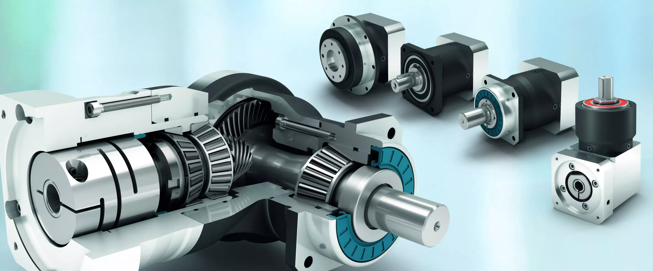
Precision planetary gear reducer is a new-generation of product developed by our company, with a compromise of advanced technology both at home and abroad, its main features are as follows:
1. Low noise: under 65db.
2. Low backlash: within 3 arcmin.
3. High efficiency: 97% for 1 stage, 94% for 2 stages.
4. High input speed: Rated input speed 3000rpm, max input speed 6000 rpm.
5. High output torque: higher torque output than that of conventional planetary gear reducer.
6. High stability hardening,which extends gear service life and maintain high accuracy as new after a long period of operation.
Precicion planetary gear reducer is widely used in the following fields:
1. Aerospace industries.
2. Medical health, electronic information industries.
3. Industrial robots, productin automation, CNC machine tool manufacturing industries.
4. Motor,textile,printing,food,metallurgical,envrironment protection engineering, warehouse logistics industries.
About Xingda since 1984
HangZhou Melchizedek Import & Export Co., Ltd. is a leader manufactur in mechanism field and punching/stamp
ing field since 1984. Our main product, NMRV worm gear speed reducer and series helical gearbox, XDR,
XDF, XDK, XDShave reached the advanced technique index of the congeneric European and Janpanese produc
ts, We offer standard gears, sprockets, chains, pulleys, couplings, bushes and so on. We also can accept orders
of non-standard products, such as gears, shafts, punching parts ect, according to customers’ Drawings or sam-
ples.
Our company has complete set of equipment including CNC, lathes, milling machines, gear hobbing machine, g-
ear grinding machine, gear honing machine, gear shaping machine, worm grinder, grinding machines, drilling m-
achines, boringmachines, planer, drawing benches, punches, hydraulic presses, plate shearing machines and s-
o on. We have advanced testing equipments also.
Our company has established favorable cooperation relationships with sub-suppliers involving casting, raw mat-
erial, heat treatment, surface finishing and so on.
| Application: | Motor, Machinery |
|---|---|
| Hardness: | Hardened Tooth Surface |
| Installation: | Vertical Type |
| Gear Shape: | Helical |
| Step: | Single-Step |
| Type: | Planetary Gear Reducer |
| Samples: |

Real-World Examples of Products Using Servo GearboxesServo gearboxes find application in various industries and products, contributing to their precision, efficiency, and performance:
These examples demonstrate the widespread adoption of servo gearboxes across various industries, where precision, accuracy, and controlled motion are critical for efficient and high-performance operations.
US$ 230/Piece
1 Piece(Min.Order) | |
|---|
| Customization: |
Available
| Customized Request |
|---|
Benefits of Using a Servo Gearbox for Precise Motion Control
Servo gearboxes offer several advantages when it comes to achieving precise motion control in various applications:
1. Accuracy: Servo gearboxes provide exceptional accuracy in speed and position control, making them suitable for applications that require tight tolerances and precise movements.
2. Low Backlash: These gearboxes are designed to minimize backlash, which is essential for eliminating lost motion and ensuring accurate positioning.
3. High Torque Density: Servo gearboxes offer a high torque-to-size ratio, allowing them to handle significant loads while maintaining a compact footprint.
4. Dynamic Performance: They excel in dynamic performance, enabling rapid changes in speed and direction with minimal overshoot or settling time.
5. Responsiveness: Servo gearboxes respond quickly to control signals, making them ideal for applications that require rapid adjustments and changes in direction.
6. Smooth Operation: These gearboxes provide smooth and precise movement, critical for applications like robotics, where jerky or uneven motion can lead to inaccuracies or damage.
7. Reduces Maintenance: The accuracy and durability of servo gearboxes can reduce wear and tear on other components, leading to lower maintenance requirements.
8. Improved Efficiency: Servo gearboxes offer high efficiency in power transmission, contributing to energy savings and minimizing heat generation.
9. Customization: They can be tailored to specific application needs, including factors like reduction ratios, mounting options, and feedback compatibility.
10. Versatility: Servo gearboxes find application in various industries, including robotics, CNC machining, medical equipment, and automation.
Overall, the benefits of using a servo gearbox for precise motion control make them an essential component in applications that demand accuracy, responsiveness, and reliable performance.


editor by CX 2023-08-14
China wholesaler High Precision Low Backlash Speed Reduction Stepper Motor Servo Motor Planetary Gearbox wholesaler
Product Description
Product Description
HPS is a leading manufacturer and supplier of planetary gearbox and gear motor in China, Our company covers an area of 6 pcs. Meanwhile, all 6 production lines strictly comply with ISO 9001 and CE to control the quality. wide-range series products have been exported to 30+ countries all over the world.
Besides, we are making great efforts to customize and provide complete solutions to meet different clients’ requirements and market. Our R&D team has 15 years experience in this field, makes our company honored with many invention patents and utility patents, which makes CZPT the most trustable and reliable manufacturer.
| SPECIFICATIONS | STAGE | RATIO | RATED TORQUE (N.m) | ||
| PLE42-L2SW Planetry Gearbox | L2 | 16 | 12 | ||
| 20 | 12 | ||||
| 25 | 12 | ||||
| 28 | 12 | ||||
| 35 | 10 | ||||
| 40 | 10 | ||||
| 50 | 10 | ||||
| 70 | 10 | ||||
| 100 | 10 | ||||
| Adapted motor | ∅5-24/ ∅22-2/F31-M3 | ||||
| Rated Input Speed (rpm) | 3000 | ||||
| Max Input Speed (rpm) | 6000 | ||||
| Backlash | L2 | ≤15 Arcmin | |||
| Fault stop torque(N.m) | 2 times of rated torque | ||||
| Efficiency | L2 | 96% | |||
| Average life span | 20000h | ||||
| Operating temperature | -10°~+90° | ||||
| Nosie | ≤55 db | ||||
| IP | 54 | ||||
| Installation method | Any installation method | ||||
Production & Test Equipments
Exhibition
HPS attends 5-6 exhibitions every year, both solar PV exhibitions and automation industry exhibitions, professional sales team and quality products build CZPT a good reputation in the market.
Certificates
Successful Projects
Packaging & Shipping
FAQ
Q1:Which areas are your products mainly used in?
A:At present, we have 2 main products: precision planetary gear reducer and solar geared motor. Most of the precision planetary reducers are used in automation fields, such as medical equipment, 3D printers, door openers, tapping machines, CNC lathes and a series of automation equipment. In addition, our solar geared motors are used in photovoltaic power generation projects, which are mainly combined with rotary drives to drive solar panels to track sunlight.
Q2: How to choose the suitable planetary gearbox?
A :First of all, we need you to be able to provide relevant parameters. If you have a motor drawing, it will let us recommend a suitable gearbox for you faster. If not, we hope you can provide the following motor parameters: output speed, output torque, voltage, current, IP, noise, operating conditions, motor size and power, etc.
Q3: What is the price ?
A : The main determining factor for the price of each product is the order volume. You can communicate with us and let us understand each other. I believe that our prices, product quality and our services can definitely make you satisfied.
Q4: Do you provide customized service?
A: Yes, we provide customized services. You only need to put CZPT your needs, and we will do our best to provide you with a plan, make plans, and try our best to meet your needs.
| Application: | Motor, Machinery, Marine, Agricultural Machinery |
|---|---|
| Function: | Change Drive Torque, Speed Changing, Speed Reduction |
| Layout: | Coaxial |
| Hardness: | Hardened Tooth Surface |
| Installation: | Any Type |
| Step: | Double-Step |
| Samples: |
US$ 45/Piece
1 Piece(Min.Order) | |
|---|
| Customization: |
Available
| Customized Request |
|---|
Servo Gearboxes vs. Standard Gearboxes in Industrial Applications
Servo gearboxes and standard gearboxes serve distinct roles in industrial applications. Here’s how they differ:
Precision Control: Servo gearboxes are specifically designed for precise motion control in applications that require accurate speed and position control. Standard gearboxes, while also providing speed reduction or torque multiplication, may not offer the same level of precision.
Backlash: Servo gearboxes are designed to minimize backlash, which is crucial for applications where even slight lost motion is unacceptable. Standard gearboxes may have higher levels of backlash due to their broader design scope.
Dynamic Response: Servo gearboxes excel in dynamic response, enabling quick changes in speed and direction with minimal overshoot. Standard gearboxes may not offer the same level of responsiveness.
High Efficiency: Servo gearboxes are optimized for efficiency to ensure precise power transmission. Standard gearboxes may prioritize other factors like cost or load capacity.
Positioning Accuracy: Servo gearboxes are essential for achieving high positioning accuracy in applications such as robotics and CNC machines. Standard gearboxes might not meet the same accuracy requirements.
Load Distribution: Servo gearboxes distribute loads evenly across gear teeth to enhance durability and minimize wear. Standard gearboxes might not have the same load distribution capabilities.
Compact Design: Servo gearboxes are often designed with a compact form factor to fit within tight spaces. Standard gearboxes might be larger and less optimized for space constraints.
Customization: Servo gearboxes can be highly customizable in terms of size, reduction ratio, and mounting options. Standard gearboxes may offer fewer customization choices.
Application Focus: Servo gearboxes are intended for applications that demand precision and responsiveness, such as robotics, automation, and CNC machining. Standard gearboxes are used in a broader range of applications where precision might not be as critical.
In summary, servo gearboxes are specialized components tailored for high-precision motion control applications, while standard gearboxes serve a wider variety of industrial needs with a focus on durability, load handling, and basic speed reduction.
editor by CX 2023-08-14
China Professional high torque planetary reducer nema 34 high precision planetary gearbox with Great quality
Applicable Industries: Building Material Shops, Manufacturing Plant, Machinery Repair Shops, Food & Beverage Factory, Farms, Home Use, Retail, Printing Shops, Construction works , Energy & Mining, Advertising Company
Gearing Arrangement: Planetary
Output Torque: 18-19000N.m
Input Speed: 1500-3000rpm
Output Speed: 1.5-1000rpm(customized)
Product name: feco
Application: automobile assembly
Ratio: 3-1000
Material of Housing: Metal
Type: for servo motor
Certificate: ISO9001
Mounting Position: Vertical (flange Mounted)
Warranty: 18 months
Heat treatment: Gear Grinding
Color: Customer Requirement
Packaging Details: Inside:carton boxes Outside:wooden cases
Port: ZheJiang
high precision and high torque nema 34 2 speed planetary gearbox
| Planetary Gearbox | |
| Efficiency | > High Torque Planetary Gearbox Mixer Drive Unit Harmonic Reducer For Concrete Mixer OEM T 90 Degree Gearbox =97% |
| Housing material | SCM415 |
| Gear material | SCM415 |
| Surface hardness of gears | 60±2HRC |
| Input / Output shaft material | SCM415 |
| Machining precision of gears | DIN6 Grade |
| Lubricating oil | KLUBER |
| Heat treatment | Carburizing, carbonitriding, brilliant quenching |
| Brand of bearings | NSK/NTN |
| Brand of oil seal | SKF/TTO |
| Noise (MAX) | 60-70dB |
| Temp. rise (MAX) | 70℃ |
| Oil Temp. rise (MAX) | 40℃ |
| Vibration | ≤15μm |
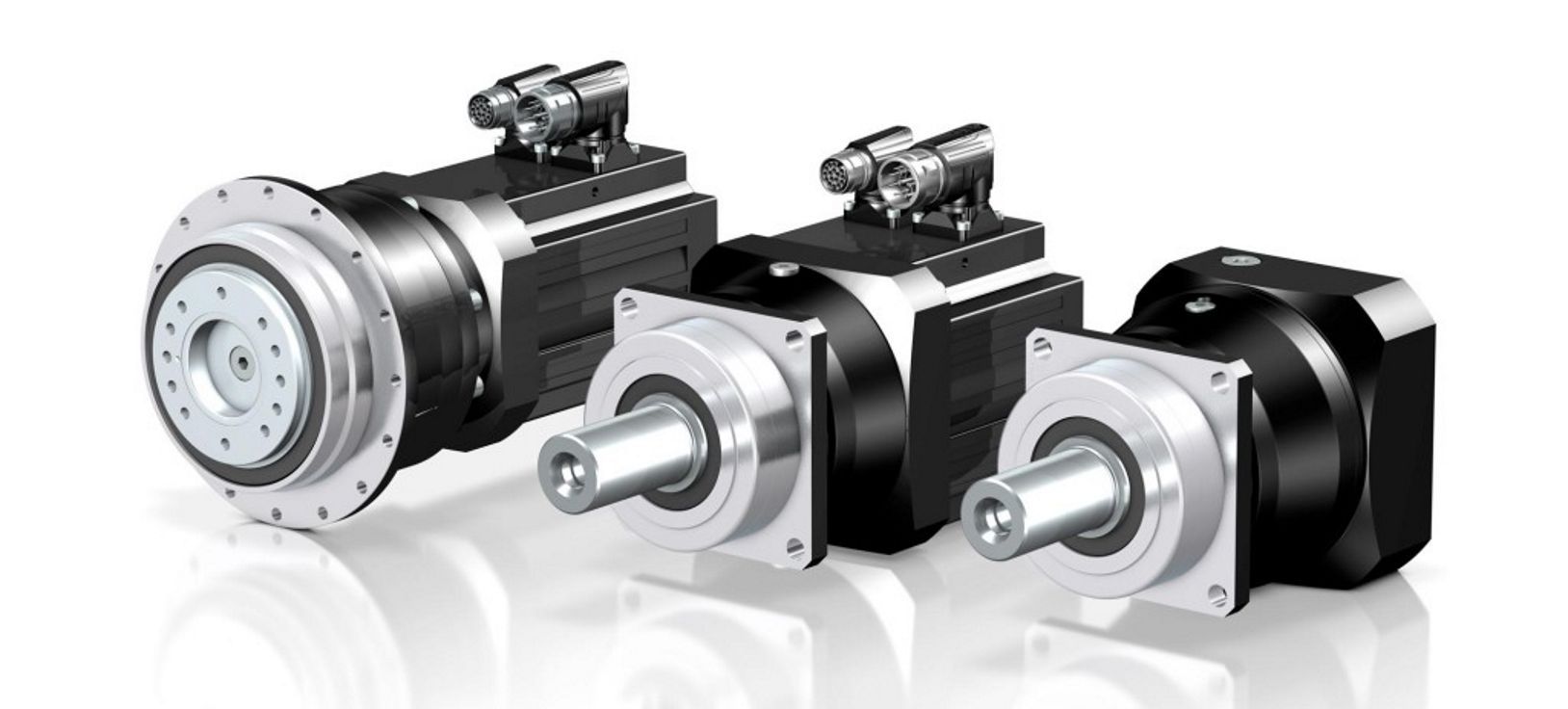
Main Features:
High precision:Adopt Japanese CZPT and HAMAYI advanced equipment.Quality and technology are strictly controlled.
High torque:(1)Front shell and tooth ring adopt integral design(2)Integrated design of planetary frame and output shaft(3)Bearing long span design, High Temperature Resistance NMRV Series 9-4 Copper Worm High Efficiency Durable Worm Gear Speed Reducer ensure the output load capacity(4) Full needle rolling, increase contact surface, increase output torque(5)Input flange interchangeability, ensure the exchange cycle(6) Modular design of motor connection plate and axle liner
Low noise:The helical tooth surface is modified for tooth shape and leadReduce the impact and noise of gear on the input and outputIncrease gear service life
Long life:NSK/NTN bearing:Steel: Japan steel (SCM415)Grease: KLUBEROil seal: SKF/TTO
Structure diagram:
Production Equipment high precision and high torque nema 34 2 speed planetary gearbox
Checkout Equipment Exhibition Our Company high precision and high torque nema 34 2 speed planetary gearbox
Related Products CH AC gear motor91.8% Response Rate
CV AC gear motor91.8% Response Rate
NMRV worm gearbox91.8% Response Rate
Packing & Delivery
| Packaging | |
| Size | Actual cargo size |
| Weight | Actual cargo size |
| Packaging Details | The normal package is wooden box(Size: L*W*H). If export to european countries,the wooden box will be fumigated.If container is too tigher,we will use pe film for packing or pack it according to customers special request. |
FAQ1. How to choose a gearbox which meets our requirement?You can refer to our catalogue to choose the gearbox or we can help to choose when you providethe technical information of required output torque, output speed and motor parameter etc.2. What information shall we give before placing a purchase order?a) Type of the gearbox, high precision planetary gearbox with servo motor ratio, input and output type, input flange, mounting position, and motor informationetc.b) Housing color.c) Purchase quantity.d) Other special requirements.3. What industries are your gearboxes being used?Our gearboxes are widely used in the areas of textile, food processing, beverage, chemical industry,escalator,automatic storage equipment, metallurgy, High quality S seties worm gear motor for sale mechanical lift worm gear screw jack design electric motor reduction gearbox tabacco, environmental protection, logistics and etc.4. Do you sell motors?We have stable motor suppliers who have been coperating with us for a long-time. They can provide motorswith high quality.
Contact us New blueprint new base.We wish to established common development with customers worldwide.
Spiral Gears for Right-Angle Right-Hand Drives
Spiral gears are used in mechanical systems to transmit torque. The bevel gear is a particular type of spiral gear. It is made up of two gears that mesh with one another. Both gears are connected by a bearing. The two gears must be in mesh alignment so that the negative thrust will push them together. If axial play occurs in the bearing, the mesh will have no backlash. Moreover, the design of the spiral gear is based on geometrical tooth forms.
Equations for spiral gear
The theory of divergence requires that the pitch cone radii of the pinion and gear be skewed in different directions. This is done by increasing the slope of the convex surface of the gear’s tooth and decreasing the slope of the concave surface of the pinion’s tooth. The pinion is a ring-shaped wheel with a central bore and a plurality of transverse axes that are offset from the axis of the spiral teeth.
Spiral bevel gears have a helical tooth flank. The spiral is consistent with the cutter curve. The spiral angle b is equal to the pitch cone’s genatrix element. The mean spiral angle bm is the angle between the genatrix element and the tooth flank. The equations in Table 2 are specific for the Spread Blade and Single Side gears from Gleason.
The tooth flank equation of a logarithmic spiral bevel gear is derived using the formation mechanism of the tooth flanks. The tangential contact force and the normal pressure angle of the logarithmic spiral bevel gear were found to be about twenty degrees and 35 degrees respectively. These two types of motion equations were used to solve the problems that arise in determining the transmission stationary. While the theory of logarithmic spiral bevel gear meshing is still in its infancy, it does provide a good starting point for understanding how it works.
This geometry has many different solutions. However, the main two are defined by the root angle of the gear and pinion and the diameter of the spiral gear. The latter is a difficult one to constrain. A 3D sketch of a bevel gear tooth is used as a reference. The radii of the tooth space profile are defined by end point constraints placed on the bottom corners of the tooth space. Then, the radii of the gear tooth are determined by the angle.
The cone distance Am of a spiral gear is also known as the tooth geometry. The cone distance should correlate with the various sections of the cutter path. The cone distance range Am must be able to correlate with the pressure angle of the flanks. The base radii of a bevel gear need not be defined, but this geometry should be considered if the bevel gear does not have a hypoid offset. When developing the tooth geometry of a spiral bevel gear, the first step is to convert the terminology to pinion instead of gear.
The normal system is more convenient for manufacturing helical gears. In addition, the helical gears must be the same helix angle. The opposite hand helical gears must mesh with each other. Likewise, the profile-shifted screw gears need more complex meshing. This gear pair can be manufactured in a similar way to a spur gear. Further, the calculations for the meshing of helical gears are presented in Table 7-1.
Design of spiral bevel gears
A proposed design of spiral bevel gears utilizes a function-to-form mapping method to determine the tooth surface geometry. This solid model is then tested with a surface deviation method to determine whether it is accurate. Compared to other right-angle gear types, spiral bevel gears are more efficient and compact. CZPT Gear Company gears comply with AGMA standards. A higher quality spiral bevel gear set achieves 99% efficiency.
A geometric meshing pair based on geometric elements is proposed and analyzed for spiral bevel gears. This approach can provide high contact strength and is insensitive to shaft angle misalignment. Geometric elements of spiral bevel gears are modeled and discussed. Contact patterns are investigated, as well as the effect of misalignment on the load capacity. In addition, a prototype of the design is fabricated and rolling tests are conducted to verify its accuracy.
The three basic elements of a spiral bevel gear are the pinion-gear pair, the input and output shafts, and the auxiliary flank. The input and output shafts are in torsion, the pinion-gear pair is in torsional rigidity, and the system elasticity is small. These factors make spiral bevel gears ideal for meshing impact. To improve meshing impact, a mathematical model is developed using the tool parameters and initial machine settings.
In recent years, several advances in manufacturing technology have been made to produce high-performance spiral bevel gears. Researchers such as Ding et al. optimized the machine settings and cutter blade profiles to eliminate tooth edge contact, and the result was an accurate and large spiral bevel gear. In fact, this process is still used today for the manufacturing of spiral bevel gears. If you are interested in this technology, you should read on!
The design of spiral bevel gears is complex and intricate, requiring the skills of expert machinists. Spiral bevel gears are the state of the art for transferring power from one system to another. Although spiral bevel gears were once difficult to manufacture, they are now common and widely used in many applications. In fact, spiral bevel gears are the gold standard for right-angle power transfer.While conventional bevel gear machinery can be used to manufacture spiral bevel gears, it is very complex to produce double bevel gears. The double spiral bevel gearset is not machinable with traditional bevel gear machinery. Consequently, novel manufacturing methods have been developed. An additive manufacturing method was used to create a prototype for a double spiral bevel gearset, and the manufacture of a multi-axis CNC machine center will follow.
Spiral bevel gears are critical components of helicopters and aerospace power plants. Their durability, endurance, and meshing performance are crucial for safety. Many researchers have turned to spiral bevel gears to address these issues. One challenge is to reduce noise, improve the transmission efficiency, and increase their endurance. For this reason, spiral bevel gears can be smaller in diameter than straight bevel gears. If you are interested in spiral bevel gears, check out this article.
Limitations to geometrically obtained tooth forms
The geometrically obtained tooth forms of a spiral gear can be calculated from a nonlinear programming problem. The tooth approach Z is the linear displacement error along the contact normal. It can be calculated using the formula given in Eq. (23) with a few additional parameters. However, the result is not accurate for small loads because the signal-to-noise ratio of the strain signal is small.
Geometrically obtained tooth forms can lead to line and point contact tooth forms. However, they have their limits when the tooth bodies invade the geometrically obtained tooth form. This is called interference of tooth profiles. While this limit can be overcome by several other methods, the geometrically obtained tooth forms are limited by the mesh and strength of the teeth. They can only be used when the meshing of the gear is adequate and the relative motion is sufficient.
During the tooth profile measurement, the relative position between the gear and the LTS will constantly change. The sensor mounting surface should be parallel to the rotational axis. The actual orientation of the sensor may differ from this ideal. This may be due to geometrical tolerances of the gear shaft support and the platform. However, this effect is minimal and is not a serious problem. So, it is possible to obtain the geometrically obtained tooth forms of spiral gear without undergoing expensive experimental procedures.
The measurement process of geometrically obtained tooth forms of a spiral gear is based on an ideal involute profile generated from the optical measurements of one end of the gear. This profile is assumed to be almost perfect based on the general orientation of the LTS and the rotation axis. There are small deviations in the pitch and yaw angles. Lower and upper bounds are determined as – 10 and -10 degrees respectively.
The tooth forms of a spiral gear are derived from replacement spur toothing. However, the tooth shape of a spiral gear is still subject to various limitations. In addition to the tooth shape, the pitch diameter also affects the angular backlash. The values of these two parameters vary for each gear in a mesh. They are related by the transmission ratio. Once this is understood, it is possible to create a gear with a corresponding tooth shape.
As the length and transverse base pitch of a spiral gear are the same, the helix angle of each profile is equal. This is crucial for engagement. An imperfect base pitch results in an uneven load sharing between the gear teeth, which leads to higher than nominal loads in some teeth. This leads to amplitude modulated vibrations and noise. In addition, the boundary point of the root fillet and involute could be reduced or eliminate contact before the tip diameter.

