Product Description
Product Description
Product Description
-R Series Helical gearbox
Product Features:
1.High modular design.
2.Integrated casting housing,compact dimension,high loading support, stable transmitting and low noise level.
3.Perfect oil leakage preventing makes the good sealings and can be used in wide range of industry.
4.This series is special for pug mill.
5.High efficiency and save power.
6.Save cost and low maintenance.
Design Features:
1. Compact structure, modular design
2. Single-stage, two-stage and three-stage sizes
3. Can be combined with other types of gearboxes (Such as R Series, K Series, F Series, S Series, UDL Series)
Product Parameters
1 Stage
| Models | Output Shaft Dia. | Input Shaft Dia. | Power(kW) | Ratio | Max. Torque(Nm) |
| BRX/BRXF38 | 20mm | 16mm | 0.18~1.1 | 1.62~4.43 | 20 |
| BRX/BRXF58 | 20mm | 19mm | 0.18~5.5 | 1.3~5.5 | 70 |
| BRX/BRXF68 | 25mm | 19mm | 0.18~7.5 | 1.4~6.07 | 135 |
| BRX/BRXF78 | 30mm | 24mm | 1.1~11 | 1.42~8.00 | 215 |
| BRX/BRXF88 | 40mm | 28mm | 3~22 | 1.39~8.65 | 400 |
| BRX/BRXF98 | 50mm | 38mm | 5.5~30 | 1.42~8.23 | 600 |
| BRX/BRXF108 | 60mm | 42mm | 7.5~45 | 1.44~6.63 | 830 |
| BRX/BRXF128 | 75mm | 55mm | 7.5~90 | 1.51~6.2 | 1110 |
| BRX/BRXF158 | 90mm | 70mm | 11~132 | 1.57~6.2 | 1680 |
2-3Stage
| Models | Output Shaft Dia. | Input Shaft Dia. | Power(kW) | Ratio | Max. Torque(Nm) |
| BR/BRF18 | 20mm | – | 0.18~0.75 | 3.83~74.84 | 85 |
| BR/BRF28 | 25mm | 16mm | 0.18~3 | 3.37~135.09 | 130 |
| BR/BRF38 | 25mm | 16mm | 0.18~3 | 3.41~134.82 | 200 |
| BR/BRF48 | 30mm | 19mm | 0.18~5.5 | 3.83~176.88 | 300 |
| BR/BRF58 | 35mm | 19mm | 0.18~7.5 | 4.39~186.89 | 450 |
| BR/BRF68 | 35mm | 19mm | 0.18~7.5 | 4.29~199.81 | 600 |
| BR/BRF78 | 40mm | 24mm | 0.18~11 | 5.21~195.24 | 820 |
| BR/BRF88 | 50mm | 28mm | 0.55~18.5 | 5.36~246.54 | 1550 |
| BR/BRF98 | 60mm | 38mm | 0.55~30 | 4.49~289.6 | 3000 |
| BR/BRF108 | 70mm | 42mm | 2.2~45 | 5.06~249.16 | 4300 |
| BR/BRF138 | 90mm | 55mm | 5.5~55 | 5.51~222.6 | 8000 |
| BR/BRF148 | 110mm | 55mm | 11~90 | 5.00~163.31 | 13000 |
| BR/BRF168 | 120mm | 70mm | 11~160 | 8.77~229.71 | 18000 |
Materials Data Sheet
|
Housing material |
Grey Cast iron |
|
Housing hardness |
HBS163~255 |
|
Gear material |
20CrMnTi alloy steel |
|
Surface hardness of gears |
HRC58°~62 ° |
|
Gear core hardness |
HRC33~48 |
|
Input / Output shaft material |
40Cr alloy steel |
|
Input / Output shaft hardness |
HRC32~36 |
|
Machining precision of gears |
accurate grinding, 6~5 Grade |
|
Lubricating oil |
GB L-CKC220-460, Shell Omala220-460 |
|
Heat treatment |
tempering, cementiting, quenching, normalizing, etc. |
|
Efficiency |
94%~96% (depends on the transmission stage) |
|
Noise (MAX) |
60~68dB |
|
Temp. rise (MAX) |
40°C |
|
Temp. rise (Oil)(MAX) |
50°C |
|
Vibration |
≤20µm |
|
Backlash |
≤20Arcmin |
|
Brand of bearings |
China top brand bearing, HRB/LYC/ZWZ/C&U. Or other brands requested, SKF, FAG, INA, NSK. |
|
Brand of oil seal |
NAK — ZheJiang or other brands requested |
Detailed Photos
Our process of production
Our product line
Company Profile
Company Profile
Bode was founded in 2007, which is located in HangZhou city, ZHangZhoug province. As 1 professional manufacturer and exporter, we have more than 17 years’ experience in R & D of worm reducer, gear reducer, gearbox , AC motor and relative spare parts. We have factory with advanced production and test equipment, the strong development of team and producing capacity offer our customers with high quality products. Our products widely served to various industries of Metallurgy, Chemicals, lifting, mining, Petroleum, textile, medicine, wooden etc. Main markets: China, Africa, Australia, Vietnam, Turkey, Japan, Korea, Philippines… Welcome to ask us any questions, good offer always for you for long term business.
FAQ
Q1: Are you trading company or manufacturer?
A: We are factory.
Q2: What kinds of gearbox can you produce for us?
A: Main products of our company: R, S, K, F series helical-tooth reducer, RV series worm gear reducer,H Series Parallel Shaft Helical Reduction Gear Box
Q3: Can you make as per custom drawing?
A: Yes, we offer customized service for customers.
Q4: Can we buy 1 pc of each item for quality testing?
A: Yes, we are glad to accept trial order for quality testing.
Q5: What information shall we give before placing a purchase order?
A: a) Type of the gearbox, ratio, input and output type, input flange, mounting position, and motor informationetc.
b) Housing color.
c) Purchase quantity.
d) Other special requirements.
Q6: How long is your delivery time?
A: Generally it is 5-10 days if the goods are in stock. or it is 15-20 days if the goods are not in stock.
Q7: What is your terms of payment ?
A: 30% Advance payment by T/T after signing the contract.70% before delivery
If you are interested in our product, welcome to contact with us.
Our team will do our best to meet your need 🙂
| Application: | Machinery, Marine, Agricultural Machinery |
|---|---|
| Function: | Distribution Power, Change Drive Torque, Speed Changing, Speed Reduction |
| Layout: | Coaxial |
| Hardness: | Hardened Tooth Surface |
| Installation: | Vertical Type |
| Step: | Single-Step |
| Samples: |
US$ 50/Piece
1 Piece(Min.Order) What are the considerations for choosing the appropriate lubrication for gear reducers?Choosing the appropriate lubrication for gear reducers is crucial for ensuring optimal performance, longevity, and efficiency. Several considerations should be taken into account when selecting the right lubrication: 1. Load and Torque: The magnitude of the load and torque transmitted by the gear reducer affects the lubrication’s viscosity and film strength requirements. Heavier loads may necessitate higher viscosity lubricants. 2. Operating Speed: The speed at which the gear reducer operates impacts the lubrication’s ability to maintain a consistent and protective film between gear surfaces. 3. Temperature Range: Consider the temperature range of the operating environment. Lubricants with suitable viscosity indexes are crucial to maintaining performance under varying temperature conditions. 4. Contaminant Exposure: If the gear reducer is exposed to dust, dirt, water, or other contaminants, the lubrication should have proper sealing properties and resistance to contamination. 5. Lubrication Interval: Determine the desired maintenance interval. Some lubricants require more frequent replacement, while others offer extended operational periods. 6. Compatibility with Materials: Ensure that the chosen lubricant is compatible with the materials used in the gear reducer, including gears, bearings, and seals. 7. Noise and Vibration: Some lubricants have properties that can help reduce noise and dampen vibrations, improving the overall user experience. 8. Environmental Impact: Consider environmental regulations and sustainability goals when selecting lubricants. 9. Manufacturer Recommendations: Follow the manufacturer’s recommendations and guidelines for lubrication type, viscosity grade, and maintenance intervals. 10. Monitoring and Analysis: Implement a lubrication monitoring and analysis program to assess lubricant condition and performance over time. By carefully evaluating these considerations and consulting with lubrication experts, industries can choose the most suitable lubrication for their gear reducers, ensuring reliable and efficient operation. | |
|---|

| Customization: |
Available
| Customized Request |
|---|

Function of Gear Reducers in Mechanical Systems
A gear reducer, also known as a gear reduction unit or gearbox, is a mechanical device designed to reduce the speed of an input shaft while increasing its torque output. It accomplishes this through the use of a set of interlocking gears with different sizes.
The primary function of a gear reducer in mechanical systems is to:
- Speed Reduction: The gear reduc

How do gear reducers handle shock loads and sudden changes in torque?
Gear reducers are designed to handle shock loads and sudden changes in torque through several mechanisms that enhance their durability and reliability in challenging operating conditions.
1. Robust Construction: Gear reducers are constructed using high-strength materials and precision manufacturing techniques. This ensures that the gears, bearings, and other components can withstand sudden impacts and high torque fluctuations without deformation or failure.
2. Shock-Absorbing Features: Some gear reducer designs incorporate shock-absorbing features, such as flexible couplings, elastomeric elements, or torsionally flexible gear designs. These features help dampen and dissipate the energy from sudden shocks or torque spikes, reducing the impact on the entire system.
3. Torque Limiters: In applications where shock loads are common, torque limiters may be integrated into the gear reducer. These devices automatically disengage or slip when a certain torque threshold is exceeded, preventing damage to the gears and other components.
4. Overload Protection: Gear reducers can be equipped with overload protection mechanisms, such as shear pins or torque sensors. These mechanisms detect excessive torque and disengage the drive temporarily, allowing the system to absorb the shock or adjust to the sudden torque change.
5. Proper Lubrication: Adequate lubrication is essential for managing shock loads and sudden torque changes. High-quality lubricants reduce friction and wear, helping the gear reducer withstand dynamic forces and maintain smooth operation.
6. Dynamic Load Distribution: Gear reducers distribute dynamic loads across multiple gear teeth, which helps prevent localized stress concentrations. This feature minimizes the risk of tooth breakage and gear damage when subjected to sudden changes in torque.
By incorporating these design features and mechanisms, gear reducers can effectively handle shock loads and sudden changes in torque, ensuring the longevity and reliability of various industrial and mechanical systems.
er takes the high-speed rotation of the input shaft and transmits it to the output shaft through a set of gears. The gears are configured in such a way that the output gear has a larger diameter than the input gear. As a result, the output shaft rotates at a lower speed than the input shaft, but with increased torque.
- Torque Increase: Due to the size difference between the input and output gears, the torque applied to the output shaft is greater than that of the input shaft. This torque multiplication allows the system to handle heavier loads and perform tasks requiring higher force.
Gear reducers are widely used in various industries and applications where it’s necessary to adapt the speed and torque characteristics of a power source to meet the requirements of the driven equipment. They can be found in machinery such as conveyor systems, industrial machinery, vehicles, and more.


editor by CX 2023-08-17
China Hot selling Da120 Helical Gear 1.5kw Servo Motor Transmission Gearbox Fubao cycloidal gearbox
Product Description
Product Description
Reducer production factory For sale helical gear 1.5KW servo motor transmission gearbox
DA series precision square flange high precision reducer. Reducer bearings are CZPT brand, gear after carbonization treatment, so the accuracy and rigidity are superior! Reducer output shaft is customized size and length according to customer requirements.
Fubao planetary gear box manufacturer, the supply of high-precision planetary reducer has the following advantages:
1, compact structure: the characteristics of large torque planetary reducer is to make full use of space, limited space design bearing and gear ratio, so that the product is smaller than the traditional reducer volume can save space.
2, high efficiency: the planetary gear group will be in a completely tight meshing state when running, reducing gear collision or local meshing resulting in gear damage. The completely tight meshing characteristic makes the efficiency loss of each gear transmission only 3%. This type of transmission mode can ensure that the kinetic energy input reducer to the mechanical end of the process, still can maintain high transmission efficiency, avoid the internal gear friction, sliding, mechanical loss.
3, high axial and radial load capacity: the output shaft of Fubao technology’s high-torque planetary reducer adopts a large-span style, so that the bearing is configured at both ends of the output shaft. The design can effectively disperse the force acting on the output shaft and reduce the load of the bearing. In other words, the product strengthens the bearing and radial load capacity under the same size.
4, high strength: large torque planetary reducer gear group is very strong and stable, the thickness of the gear dispersed the load on the gear. The large span bearing group provides a stable structure, and the precision gear group allows the load to be distributed to each planetary gear under tight meshing to withstand the torque load.
5, high stability: precision processing to ensure that the product coaxial and concentric, coupled with bearing large span design, so that large torque planetary reducer with excellent stability.
Product Parameters
| DA series parameters | Model number | DA60 | DA090 | DA120 | DA150 | |
| Rated output torque | 40~60Nm | 120~340Nm | 230~340Nm | 450~650Nm | ||
| Reduction ratio | L1:3,5,7,10 L2:9,12,15,16,20,21,25,28,30,30,40,49,50,70 | |||||
| Planetary gear backlash | L1PO:≤1 P1≤3 P2≤5 L2 P0≤3 P1≤5 P2≤7 | |||||
Detailed Photos
Product Classification
Company Profile
Factory Display
Q: Speed reducer grease replacement time
A: When sealing appropriate amount of grease and running reducer, the standard replacement time is 20000 hours according to the aging condition of the grease. In addition, when the grease is stained or used in the surrounding temperature condition (above 40ºC), please check the aging and fouling of the grease, and specify the replacement time.
Q: Delivery time
A: Fubao has 2000+ production base, daily output of 1000+ units, standard models within 7 days of delivery.
Q: Reducer selection
A: Fubao provides professional product selection guidance, with higher product matching degree, higher cost performance and higher utilization rate.
Q: Application range of reducer
A: Fubao has a professional research and development team, complete category design, can match any stepping motor, servo motor, more accurate matching.
|
Shipping Cost:
Estimated freight per unit. |
To be negotiated |
|---|
| Application: | Motor, Machinery, Agricultural Machinery, Mechanical Equipment |
|---|---|
| Function: | Distribution Power, Change Drive Torque, Speed Changing, Speed Reduction, Reduce Motor Speed |
| Layout: | Cycloidal |
| Customization: |
Available
| Customized Request |
|---|

Servo Gearbox: Function in Motion Control Systems
A servo gearbox is a specialized type of gearbox designed to work in conjunction with servo motors to achieve precise motion control in various applications. It functions as follows:
Motion Synchronization: A servo gearbox is used to synchronize the motion of a servo motor with the intended motion of a mechanical system. It ensures that the motor’s rotational output is accurately transmitted to the driven component.
Speed and Position Control: Servo gearboxes enable precise control over speed and position by converting the high-speed, low-torque output of a servo motor into a lower-speed, higher-torque output suitable for the specific application.
Reduction Ratio: The servo gearbox incorporates reduction stages to achieve the desired reduction ratio. This reduction allows the motor to provide higher torque while maintaining accurate speed control.
Backlash Minimization: High-precision servo gearboxes are designed to minimize backlash, which is the lost motion between input and output shafts. This is critical for accurate and responsive motion control.
High Efficiency: Servo gearboxes are designed for high efficiency to ensure that the majority of input power is effectively transferred to the output, reducing energy consumption.
Dynamic Response: Servo gearboxes enhance the dynamic response of motion control systems. They allow the servo motor to quickly start, stop, and change directions with minimal overshooting or oscillations.
Positioning Accuracy: By accurately converting the motor’s rotation into precise linear or angular movement, servo gearboxes ensure high positioning accuracy required in applications such as robotics, CNC machines, and automation systems.
Load Distribution: Servo gearboxes distribute the load evenly across gear teeth, enhancing the gearbox’s durability and minimizing wear.
Customization: Servo gearboxes are available in various sizes, reduction ratios, and configurations to suit different application requirements.
Overall, a servo gearbox is an integral component in motion control systems, allowing precise and efficient control over motion, speed, and position for a wide range of industrial applications.
editor by CX 2023-08-17
China Best Sales Rx Series Foot-Mounted Single-Stage Helical Gear Unit with CZPT Shaft Reducer Gearbox supplier
Product Description
Product Description
Product Description
-R Series Helical gearbox
Product Features:
1.High modular design.
2.Integrated casting housing,compact dimension,high loading support, stable transmitting and low noise level.
3.Perfect oil leakage preventing makes the good sealings and can be used in wide range of industry.
4.This series is special for pug mill.
5.High efficiency and save power.
6.Save cost and low maintenance.
Design Features:
1. Compact structure, modular design
2. Single-stage, two-stage and three-stage sizes
3. Can be combined with other types of gearboxes (Such as R Series, K Series, F Series, S Series, UDL Series)
Product Parameters
1 Stage
| Models | Output Shaft Dia. | Input Shaft Dia. | Power(kW) | Ratio | Max. Torque(Nm) |
| BRX/BRXF38 | 20mm | 16mm | 0.18~1.1 | 1.62~4.43 | 20 |
| BRX/BRXF58 | 20mm | 19mm | 0.18~5.5 | 1.3~5.5 | 70 |
| BRX/BRXF68 | 25mm | 19mm | 0.18~7.5 | 1.4~6.07 | 135 |
| BRX/BRXF78 | 30mm | 24mm | 1.1~11 | 1.42~8.00 | 215 |
| BRX/BRXF88 | 40mm | 28mm | 3~22 | 1.39~8.65 | 400 |
| BRX/BRXF98 | 50mm | 38mm | 5.5~30 | 1.42~8.23 | 600 |
| BRX/BRXF108 | 60mm | 42mm | 7.5~45 | 1.44~6.63 | 830 |
| BRX/BRXF128 | 75mm | 55mm | 7.5~90 | 1.51~6.2 | 1110 |
| BRX/BRXF158 | 90mm | 70mm | 11~132 | 1.57~6.2 | 1680 |
2-3Stage
| Models | Output Shaft Dia. | Input Shaft Dia. | Power(kW) | Ratio | Max. Torque(Nm) |
| BR/BRF18 | 20mm | – | 0.18~0.75 | 3.83~74.84 | 85 |
| BR/BRF28 | 25mm | 16mm | 0.18~3 | 3.37~135.09 | 130 |
| BR/BRF38 | 25mm | 16mm | 0.18~3 | 3.41~134.82 | 200 |
| BR/BRF48 | 30mm | 19mm | 0.18~5.5 | 3.83~176.88 | 300 |
| BR/BRF58 | 35mm | 19mm | 0.18~7.5 | 4.39~186.89 | 450 |
| BR/BRF68 | 35mm | 19mm | 0.18~7.5 | 4.29~199.81 | 600 |
| BR/BRF78 | 40mm | 24mm | 0.18~11 | 5.21~195.24 | 820 |
| BR/BRF88 | 50mm | 28mm | 0.55~18.5 | 5.36~246.54 | 1550 |
| BR/BRF98 | 60mm | 38mm | 0.55~30 | 4.49~289.6 | 3000 |
| BR/BRF108 | 70mm | 42mm | 2.2~45 | 5.06~249.16 | 4300 |
| BR/BRF138 | 90mm | 55mm | 5.5~55 | 5.51~222.6 | 8000 |
| BR/BRF148 | 110mm | 55mm | 11~90 | 5.00~163.31 | 13000 |
| BR/BRF168 | 120mm | 70mm | 11~160 | 8.77~229.71 | 18000 |
Materials Data Sheet
|
Housing material |
Grey Cast iron |
|
Housing hardness |
HBS163~255 |
|
Gear material |
20CrMnTi alloy steel |
|
Surface hardness of gears |
HRC58°~62 ° |
|
Gear core hardness |
HRC33~48 |
|
Input / Output shaft material |
40Cr alloy steel |
|
Input / Output shaft hardness |
HRC32~36 |
|
Machining precision of gears |
accurate grinding, 6~5 Grade |
|
Lubricating oil |
GB L-CKC220-460, Shell Omala220-460 |
|
Heat treatment |
tempering, cementiting, quenching, normalizing, etc. |
|
Efficiency |
94%~96% (depends on the transmission stage) |
|
Noise (MAX) |
60~68dB |
|
Temp. rise (MAX) |
40°C |
|
Temp. rise (Oil)(MAX) |
50°C |
|
Vibration |
≤20µm |
|
Backlash |
≤20Arcmin |
|
Brand of bearings |
China top brand bearing, HRB/LYC/ZWZ/C&U. Or other brands requested, SKF, FAG, INA, NSK. |
|
Brand of oil seal |
NAK — ZheJiang or other brands requested |
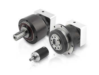
Detailed Photos
Our process of production
Our product line
Company Profile
Company Profile
Bode was founded in 2007, which is located in HangZhou city, ZHangZhoug province. As 1 professional manufacturer and exporter, we have more than 17 years’ experience in R & D of worm reducer, gear reducer, gearbox , AC motor and relative spare parts. We have factory with advanced production and test equipment, the strong development of team and producing capacity offer our customers with high quality products. Our products widely served to various industries of Metallurgy, Chemicals, lifting, mining, Petroleum, textile, medicine, wooden etc. Main markets: China, Africa, Australia, Vietnam, Turkey, Japan, Korea, Philippines… Welcome to ask us any questions, good offer always for you for long term business.
FAQ
Q1: Are you trading company or manufacturer?
A: We are factory.
Q2: What kinds of gearbox can you produce for us?
A: Main products of our company: R, S, K, F series helical-tooth reducer, RV series worm gear reducer,H Series Parallel Shaft Helical Reduction Gear Box
Q3: Can you make as per custom drawing?
A: Yes, we offer customized service for customers.
Q4: Can we buy 1 pc of each item for quality testing?
A: Yes, we are glad to accept trial order for quality testing.
Q5: What information shall we give before placing a purchase order?
A: a) Type of the gearbox, ratio, input and output type, input flange, mounting position, and motor informationetc.
b) Housing color.
c) Purchase quantity.
d) Other special requirements.
Q6: How long is your delivery time?
A: Generally it is 5-10 days if the goods are in stock. or it is 15-20 days if the goods are not in stock.
Q7: What is your terms of payment ?
A: 30% Advance payment by T/T after signing the contract.70% before delivery
If you are interested in our product, welcome to contact with us.
Our team will do our best to meet your need 🙂
| Application: | Machinery, Marine, Agricultural Machinery |
|---|---|
| Function: | Distribution Power, Change Drive Torque, Speed Changing, Speed Reduction |
| Layout: | Coaxial |
| Hardness: | Hardened Tooth Surface |
| Installation: | Vertical Type |
| Step: | Single-Step |
| Samples: |
US$ 50/Piece
1 Piece(Min.Order) | What factors should be considered when selecting the right gear reducer?Choosing the appropriate gear reducer involves considering several crucial factors to ensure optimal performance and efficiency for your specific application:
By carefully assessing these factors and consulting with gear reducer manufacturers, engineers and industry professionals can make informed decisions to select the right gear reducer for their specific application, optimizing performance, longevity, and cost-effectiveness. |
|---|

| Customization: |
Available
| Customized Request How do manufacturers ensure the precision of gear tooth profiles in gear reducers?Manufacturers employ several techniques to ensure the precision of gear tooth profiles in gear reducers, which is crucial for optimal performance and efficiency: 1. Precision Machining: Gear teeth are typically machined using advanced CNC (Computer Numerical Control) machines that can achieve high levels of accuracy and repeatability. This ensures consistent gear tooth profiles across multiple components. 2. Quality Control Measures: Rigorous quality control processes, such as dimensional inspections and profile measurements, are performed at various stages of manufacturing to verify that gear tooth profiles meet the required specifications. 3. Tooth Profile Design: Engineers use specialized software and simulation tools to design gear tooth profiles with precise involute shapes and accurate dimensions. These designs are then translated into machine instructions for manufacturing. 4. Material Selection: High-quality materials with excellent wear resistance and dimensional stability are chosen to minimize the potential for deformation or inaccuracies during machining and operation. 5. Heat Treatment: Heat treatment processes, such as carburizing and quenching, are applied to enhance the surface hardness and durability of gear teeth, reducing the risk of wear and deformation over time. 6. Tooth Grinding and Finishing: After initial machining, gear teeth often undergo precision grinding and finishing processes to achieve the desired tooth profile accuracy and surface finish. 7. Post-Processing Inspection: Gear tooth profiles are inspected again after manufacturing processes to verify that the final components meet the specified tolerances and performance criteria. 8. Computer-Aided Manufacturing (CAM): CAM software is used to generate tool paths and machining instructions, enabling precise control over tool movements and material removal during gear manufacturing. By combining these techniques and leveraging advanced manufacturing technologies, manufacturers can achieve the necessary precision in gear tooth profiles, resulting in reliable and efficient gear reducers for various industrial applications. |
|---|

How do gear reducers contribute to speed reduction and torque increase?
Gear reducers play a crucial role in mechanical systems by achieving speed reduction and torque increase through the principle of gear ratios. Here’s how they work:
Gear reducers consist of multiple gears with different sizes, known as gear pairs. These gears are meshed together, and their teeth interlock to transmit motion and power. The gear ratio is determined by the ratio of the number of teeth on the input gear (driver) to the number of teeth on the output gear (driven).
Speed Reduction: When a larger gear (output gear) is driven by a smaller gear (input gear), the output gear rotates at a slower speed than the input gear. This reduction in speed is proportional to the gear ratio. As a result, gear reducers are used to slow down the rotational speed of the output shaft compared to the input shaft.
Torque Increase: The interlocking teeth of gears create a mechanical advantage that allows gear reducers to increase torque output. When the input gear applies a force (torque) to the teeth, it is transmitted to the output gear with greater force due to the leverage provided by the larger diameter of the output gear. The torque increase is inversely proportional to the gear ratio and is essential for applications requiring high torque at lower speeds.
By selecting appropriate gear ratios and arranging gear pairs, gear reducers can achieve various speed reduction and torque multiplication factors, making them essential components in machinery and equipment where precise control of speed and torque is necessary.
editor by CX 2023-08-16
China high quality Da120 Helical Gear 1.5kw Servo Motor Transmission Gearbox Fubao manufacturer
Product Description
Product Description
Reducer production factory For sale helical gear 1.5KW servo motor transmission gearbox
DA series precision square flange high precision reducer. Reducer bearings are CZPT brand, gear after carbonization treatment, so the accuracy and rigidity are superior! Reducer output shaft is customized size and length according to customer requirements.
Fubao planetary gear box manufacturer, the supply of high-precision planetary reducer has the following advantages:
1, compact structure: the characteristics of large torque planetary reducer is to make full use of space, limited space design bearing and gear ratio, so that the product is smaller than the traditional reducer volume can save space.
2, high efficiency: the planetary gear group will be in a completely tight meshing state when running, reducing gear collision or local meshing resulting in gear damage. The completely tight meshing characteristic makes the efficiency loss of each gear transmission only 3%. This type of transmission mode can ensure that the kinetic energy input reducer to the mechanical end of the process, still can maintain high transmission efficiency, avoid the internal gear friction, sliding, mechanical loss.
3, high axial and radial load capacity: the output shaft of Fubao technology’s high-torque planetary reducer adopts a large-span style, so that the bearing is configured at both ends of the output shaft. The design can effectively disperse the force acting on the output shaft and reduce the load of the bearing. In other words, the product strengthens the bearing and radial load capacity under the same size.
4, high strength: large torque planetary reducer gear group is very strong and stable, the thickness of the gear dispersed the load on the gear. The large span bearing group provides a stable structure, and the precision gear group allows the load to be distributed to each planetary gear under tight meshing to withstand the torque load.
5, high stability: precision processing to ensure that the product coaxial and concentric, coupled with bearing large span design, so that large torque planetary reducer with excellent stability.
Product Parameters
| DA series parameters | Model number | DA60 | DA090 | DA120 | DA150 | |
| Rated output torque | 40~60Nm | 120~340Nm | 230~340Nm | 450~650Nm | ||
| Reduction ratio | L1:3,5,7,10 L2:9,12,15,16,20,21,25,28,30,30,40,49,50,70 | |||||
| Planetary gear backlash | L1PO:≤1 P1≤3 P2≤5 L2 P0≤3 P1≤5 P2≤7 | |||||
Detailed Photos
Product Classification
Company Profile
Factory Display
Q: Speed reducer grease replacement time
A: When sealing appropriate amount of grease and running reducer, the standard replacement time is 20000 hours according to the aging condition of the grease. In addition, when the grease is stained or used in the surrounding temperature condition (above 40ºC), please check the aging and fouling of the grease, and specify the replacement time.
Q: Delivery time
A: Fubao has 2000+ production base, daily output of 1000+ units, standard models within 7 days of delivery.
Q: Reducer selection
A: Fubao provides professional product selection guidance, with higher product matching degree, higher cost performance and higher utilization rate.
Q: Application range of reducer
A: Fubao has a professional research and development team, complete category design, can match any stepping motor, servo motor, more accurate matching.
|
Shipping Cost:
Estimated freight per unit. |
To be negotiated |
|---|
| Application: | Motor, Machinery, Agricultural Machinery, Mechanical Equipment |
|---|---|
| Function: | Distribution Power, Change Drive Torque, Speed Changing, Speed Reduction, Reduce Motor Speed |
| Layout: | Cycloidal |
| Customization: |
Available
| Customized Request |
|---|
Servo Gearbox: Function in Motion Control Systems
A servo gearbox is a specialized type of gearbox designed to work in conjunction with servo motors to achieve precise motion control in various applications. It functions as follows:
Motio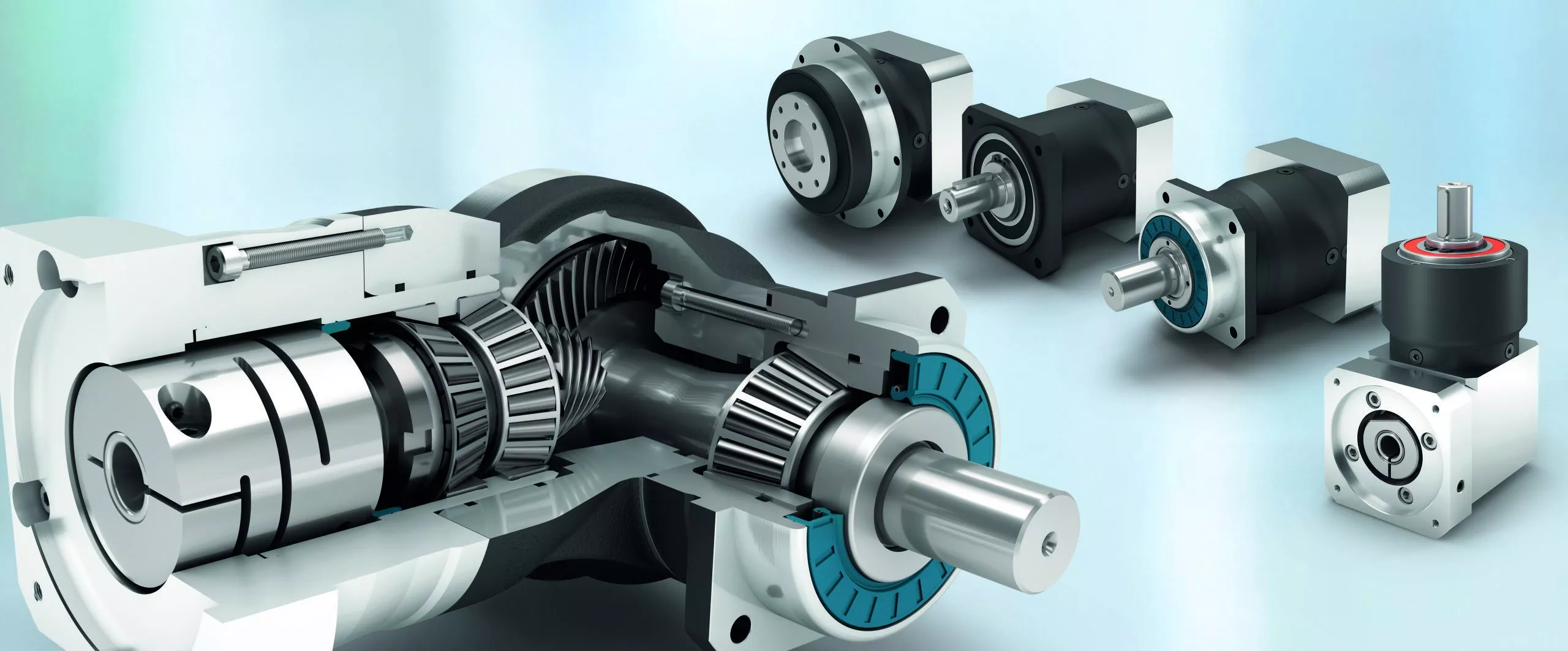
Handling Sudden Changes in Direction and Speed with Servo Gearboxes
Servo gearboxes are designed to handle sudden changes in direction and speed effectively, ensuring precise motion control even during dynamic operations. They employ several mechanisms to address these challenges:
1. Acceleration and Deceleration Profiles: Servo systems can be programmed with specific acceleration and deceleration profiles. This means that when a sudden change in speed or direction is commanded, the system can ramp up or down the speed smoothly, reducing the impact of sudden changes on the mechanical components.
2. Closed-Loop Control: Servo systems operate in a closed-loop configuration, where feedback sensors continuously monitor the actual position and speed of the system. When a sudden change is commanded, the controller can make real-time adjustments to ensure the system reaches the desired position accurately and smoothly.
3. Torque Control: Servo gearboxes are designed to provide high torque output even at low speeds. This is crucial for handling sudden changes in direction and speed, as the gearbox can deliver the required torque to quickly accelerate or decelerate the load.
4. Dynamic Response: Servo systems have fast dynamic response capabilities, which means they can quickly adapt to changes in input commands. This responsiveness allows the system to handle sudden changes in direction and speed without sacrificing accuracy or stability.
5. Electronic Damping: Some advanced servo systems incorporate electronic damping mechanisms that can be adjusted based on the application’s requirements. This feature helps dampen vibrations and oscillations that may occur during sudden changes in motion.
6. Overcurrent and Overvoltage Protection: Servo systems are equipped with protection mechanisms that detect excessive currents or voltages. If a sudden change in direction or speed causes abnormal loads or voltages, the system can take corrective actions to prevent damage.
Overall, servo gearboxes excel in handling sudden changes in direction and speed by leveraging their closed-loop control, high torque output, and fast dynamic response capabilities. These features allow them to provide accurate and reliable motion control in dynamic and rapidly changing operating conditions.
n Synchronization: A servo gearbox is used to synchronize the motion of a servo motor with the intended motion of a mechanical system. It ensures that the motor’s rotational output is accurately transmitted to the driven component.
Speed and Position Control: Servo gearboxes enable precise cont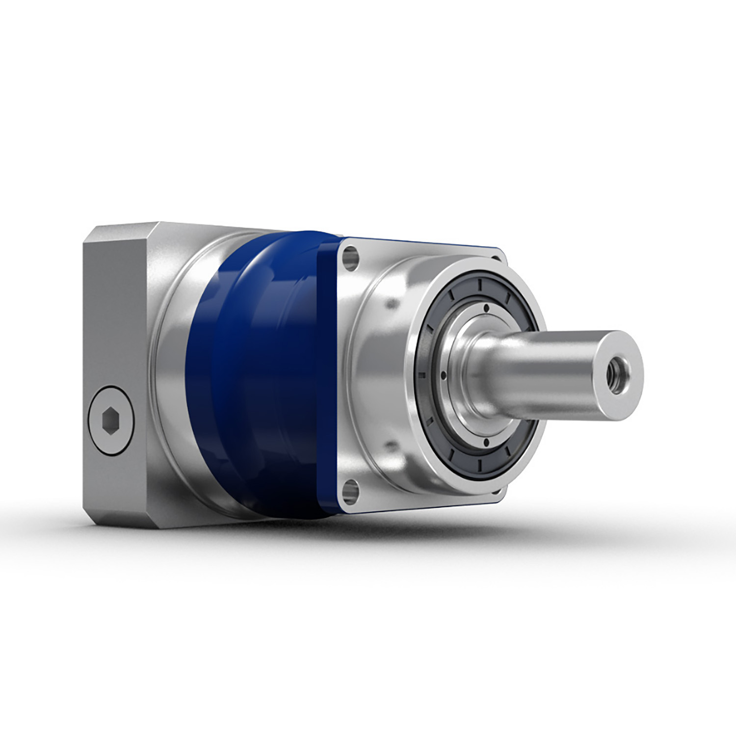
Customization of Servo Gearboxes for Specific Industrial Needs
Servo gearboxes can indeed be customized to meet specific industrial requirements. Manufacturers offer customization options to ensure that the servo gearboxes are optimized for the intended applications:
1. Gear Ratio Selection: Depending on the desired speed and torque output, manufacturers can provide various gear ratios to achieve the required motion characteristics.
2. Torque and Speed Ratings: Servo gearboxes can be tailored to handle different torque and speed demands, ensuring that they can efficiently operate within the specified parameters of the application.
3. Mounting Configurations: Manufacturers offer various mounting options, such as flange mounts or shaft mounts, to suit the mechanical layout of the machinery.
4. Output Shaft Configuration: Custom output shaft configurations, such as different diameters or keyway options, can be provided based on the integration requirements.
5. Environmental Considerations: For applications with specific environmental conditions, such as high humidity or extreme temperatures, servo gearboxes can be designed with protective features or special coatings.
6. Lubrication and Sealing: Custom lubrication options and sealing mechanisms can be incorporated to ensure optimal performance and longevity in the given environment.
7. Feedback Devices: Some applications may require specific feedback devices, such as encoders or resolvers, for precise motion control. Manufacturers can integrate these devices into the gearbox design.
8. Noise Reduction: Customized designs can include features that reduce noise and vibration, which is crucial in noise-sensitive applications.
9. Compact Designs: Manufacturers can work on compact designs to accommodate space constraints in the machinery.
10. Integration with Motors: Customized servo gearboxes can be designed to seamlessly integrate with specific types of motors, ensuring efficient power transmission.
By offering customization options, manufacturers enable industries to obtain servo gearboxes that perfectly align with their unique industrial needs, ultimately enhancing performance, precision, and overall system efficiency.
rol over speed and position by converting the high-speed, low-torque output of a servo motor into a lower-speed, higher-torque output suitable for the specific application.
Reduction Ratio: The servo gearbox incorporates reduction stages to achieve the desired reduction ratio. This reduction allows the motor to provide higher torque while maintaining accurate speed control.
Backlash Minimization: High-precision servo gearboxes are designed to minimize backlash, which is the lost motion between input and output shafts. This is critical for accurate and responsive motion control.
High Efficiency: Servo gearboxes are designed for high efficiency to ensure that the majority of input power is effectively transferred to the output, reducing energy consumption.
Dynamic Response: Servo gearboxes enhance the dynamic response of motion control systems. They allow the servo motor to quickly start, stop, and change directions with minimal overshooting or oscillations.
Positioning Accuracy: By accurately converting the motor’s rotation into precise linear or angular movement, servo gearboxes ensure high positioning accuracy required in applications such as robotics, CNC machines, and automation systems.
Load Distribution: Servo gearboxes distribute the load evenly across gear teeth, enhancing the gearbox’s durability and minimizing wear.
Customization: Servo gearboxes are available in various sizes, reduction ratios, and configurations to suit different application requirements.
Overall, a servo gearbox is an integral component in motion control systems, allowing precise and efficient control over motion, speed, and position for a wide range of industrial applications.
editor by CX 2023-08-16
China Best Sales KAF57 gearbox K Series high torque low rpm helical bevel electric motor speed gearbox near me factory
Warranty: 1 year
Applicable Industries: Hotels, Garment Shops, Building Material Shops, Manufacturing Plant, Machinery Repair Shops, Food & Beverage Factory, Farms, Restaurant, Home Use, Retail, Food Shop, Printing Shops, Construction works , Energy & Mining, Food & Beverage Shops, Other, Advertising Company
Weight (KG): 35 KG
Customized support: OEM, ODM, OBM
Gearing Arrangement: Helical
Output Torque: 800~100000N.m
Input Speed: 1400rpm
Output Speed: 14-280rpm
Ratio: 7.5~100
Certification: ISO9001-2008
Mount Position: Foot Mounted
Bearing: LYC,SKF
Packaging Details: Wooden boxes , Cantons packed in 1 pallet
Specification itemvalueWarranty1 yearApplicable IndustriesHotels, Garment Shops, Building Material Shops, Manufacturing Plant, Machinery Repair Shops, Food & Beverage Factory, Farms, Restaurant, Home Use, Retail, Food Shop, Printing Shops, dia 37mm gearbox motor 12v low rpm electric gear dc motor Construction works , Energy & Mining, Food & Beverage Shops, Other, Advertising CompanyCustomized supportOEM, ODM, OBMGearing ArrangementHelicalOutput Torque800~100000N.mInput Speed1400rpmOutput Speed14-280rpmPlace of OriginChinaBrand NameSanLianRatio7.5~100CertificationISO9001-2008Mount PositionFoot MountedBearingLYC,SKF Packing & Delivery Wooden boxes , Cantons packed in 1 palletUSE IN Company Profile Founded in 2015, HangZhou Xihu (West Lake) Dis. Imp. & Exp. Co., Ltd is a professional trade company of reducer, Our company covers an area of 40,000 square meters and there are 800 employees, 20% of whom are technicians. We are well equipped with 300 sets of advanced CNC lathe, machining centers, German HOFLER forming gear grinding machine and advanced detection equipment. We commit ourselves to provide clients with perfect products and service. Our products exported to more than 30 countries in America, Europe, Asia, Middle East and Africa, are enjoying high reputation over the world. FAQ 1. who are we?We are based in ZHangZhoug, China, start from 2015,sell to Southeast Asia(25.00%),Western Europe(20.00%),Africa(15.00%),Central America(15.00%),Southern Europe(13.00%),South America(5.00%),South Asia(4.00%), Factory price 24v 48v 400W~1500W mini transaxle electric motor dc with axle hot sale Northern Europe(2.00%),Domestic Market(60.00%),Eastern Asia(20.00%),Mid East(10.00%),Eastern Europe(5.00%),Oceania(5.00%). There are total about 11-50 people in our office.2. how can we guarantee quality?Always a pre-production sample before mass production;Always final Inspection before shipment;3.what can you buy from us?Gearbox,Gear,Forging,Transmission chains & sprockets and other transmission parts4. why should you buy from us not from other suppliers?HangZhou Xihu (West Lake) Dis. Imp. & Exp. Co., Ltd is the subcompany of CZPT Transmission Machinery Co., Ltd.. It is a professional manufacturer of gearbox for more than 31 years.and 1 step source for transmission produces.5. what services can we provide?Accepted Delivery Terms: FOB,CFR,CIF;Accepted Payment Currency:USD,EUR;Accepted Payment Type: T/T,L/C,MoneyGram,PayPal,Western Union;Language Spoken:English,Chinese VR Exhibition Contact Us Title goes here.Hi My Friend,I am Shadow Lin, will serving your for reducers and transmission parts in future!Don’t worry if you don’t know how to choose!Our have a group help you to choose!Don’ Y2 80M12 0.75kw powerful electric motor t worry if you want to customized!Our have a design group help to count and design.
Key Market Insights Related to Worm Reduction Gearboxes
A gearbox is a mechanical device that allows you to shift between different speeds or gears. It does so by using one or more clutches. Some gearboxes are single-clutch, while others use two clutches. You can even find a gearbox with closed bladders. These are also known as dual clutches and can shift gears more quickly than other types. Performance cars are designed with these types of gearboxes.
Backlash measurement
Gearbox backlash is a common component that can cause noise or other problems in a car. In fact, the beats and sets of gears in a gearbox are often excited by the oscillations of the engine torque. Noise from gearboxes can be significant, particularly in secondary shafts that engage output gears with a differential ring. To measure backlash and other dimensional variations, an operator can periodically take the output shaft’s motion and compare it to a known value.
A comparator measures the angular displacement between two gears and displays the results. In one method, a secondary shaft is disengaged from the gearbox and a control gauge is attached to its end. A threaded pin is used to secure the differential crown to the secondary shaft. The output pinion is engaged with the differential ring with the aid of a control gauge. The angular displacement of the secondary shaft is then measured by using the dimensions of the output pinion.
Backlash measurements are important to ensure the smooth rotation of meshed gears. There are various types of backlash, which are classified according to the type of gear used. The first type is called circumferential backlash, which is the length of the pitch circle around which the gear rotates to make contact. The second type, angular backlash, is defined as the maximum angle of movement between two meshed gears, which allows the other gear to move when the other gear is stationary.
The backlash measurement for gearbox is one of the most important tests in the manufacturing process. It is a criterion of tightness or looseness in a gear set, and too much backlash can jam a gear set, causing it to interface on the weaker part of its gear teeth. When backlash is too tight, it can lead to gears jamming under thermal expansion. On the other hand, too much backlash is bad for performance.
Worm reduction gearboxes
Worm reduction gearboxes are used in the production of many different kinds of machines, including steel and power plants. They are also used extensively in the sugar and paper industries. The company is constantly aiming to improve their products and services to remain competitive in the global marketplace. The following is a summary of key market insights related to this type of gearbox. This report will help you make informed business decisions. Read on to learn more about the advantages of this type of gearbox.
Compared to conventional gear sets, worm reduction gearboxes have few disadvantages. Worm gear reducers are commonly available and manufacturers have standardized their mounting dimensions. There are no unique requirements for shaft length, height, and diameter. This makes them a very versatile piece of equipment. You can choose to use one or combine several worm gear reducers to fit your specific application. And because they have standardized ratios, you will not have to worry about matching up multiple gears and determining which ones fit.
One of the primary disadvantages of worm reduction gearboxes is their reduced efficiency. Worm reduction gearboxes usually have a maximum reduction ratio of five to sixty. The higher-performance hypoid gears have an output speed of around ten to twelve revolutions. In these cases, the reduced ratios are lower than those with conventional gearing. Worm reduction gearboxes are generally more efficient than hypoid gear sets, but they still have a low efficiency.
The worm reduction gearboxes have many advantages over traditional gearboxes. They are simple to maintain and can work in a range of different applications. Because of their reduced speed, they are perfect for conveyor belt systems.
Worm reduction gearboxes with closed bladders
The worm and the gear mesh with each other in a combination of sliding and rolling movements. This sliding action is dominant at high reduction ratios, and the worm and gear are made of dissimilar metals, which results in friction and heat. This limits the efficiency of worm gears to around thirty to fifty percent. A softer material for the gear can be used to absorb shock loads during operation.
A normal gear changes its output independently once a sufficient load is applied. However, the backstop complicates the gear configuration. Worm gears require lubrication because of the sliding wear and friction introduced during movement. A common gear arrangement moves power at the peak load section of a tooth. The sliding happens at low speeds on either side of the apex and occurs at a low velocity.
Single-reduction gearboxes with closed bladders may not require a drain plug. The reservoir for a worm gear reducer is designed so that the gears are in constant contact with lubricant. However, the closed bladders will cause the worm gear to wear out more quickly, which can cause premature wear and increased energy consumption. In this case, the gears can be replaced.
Worm gears are commonly used for speed reduction applications. Unlike conventional gear sets, worm gears have higher reduction ratios. The number of gear teeth in the worm reduces the speed of a particular motor by a substantial amount. This makes worm gears an attractive option for hoisting applications. In addition to their increased efficiency, worm gears are compact and less prone to mechanical failure.
Shaft arrangement of a gearbox
The ray-diagram of a gearbox shows the arrangement of gears in the various shafts of the transmission. It also shows how the transmission produces different output speeds from a single speed. The ratios that represent the speed of the spindle are called the step ratio and the progression. A French engineer named Charles Renard introduced five basic series of gearbox speeds. The first series is the gear ratio and the second series is the reverse gear ratio.
The layout of the gear axle system in a gearbox relates to its speed ratio. In general, the speed ratio and the centre distance are coupled by the gear axles to form an efficient transmission. Other factors that may affect the layout of the gear axles include space constraints, the axial dimension, and the stressed equilibrium. In October 2009, the inventors of a manual transmission disclosed the invention as No. 2. These gears can be used to realize accurate gear ratios.
The input shaft 4 in the gear housing 16 is arranged radially with the gearbox output shaft. It drives the lubricating oil pump 2. The pump draws oil from a filter and container 21. It then delivers the lubricating oil into the rotation chamber 3. The chamber extends along the longitudinal direction of the gearbox input shaft 4, and it expands to its maximum diameter. The chamber is relatively large, due to a detent 43.
Different configurations of gearboxes are based on their mounting. The mounting of gearboxes to the driven equipment dictates the arrangement of shafts in the gearbox. In certain cases, space constraints also affect the shaft arrangement. This is the reason why the input shaft in a gearbox may be offset horizontally or vertically. However, the input shaft is hollow, so that it can be connected to lead through lines or clamping sets.
Mounting of a gearbox
In the mathematical model of a gearbox, the mounting is defined as the relationship between the input and output shafts. This is also known as the Rotational Mount. It is one of the most popular types of models used for drivetrain simulation. This model is a simplified form of the rotational mount, which can be used in a reduced drivetrain model with physical parameters. The parameters that define the rotational mount are the TaiOut and TaiIn of the input and output shaft. The Rotational Mount is used to model torques between these two shafts.
The proper mounting of a gearbox is crucial for the performance of the machine. If the gearbox is not aligned properly, it may result in excessive stress and wear. It may also result in malfunctioning of the associated device. Improper mounting also increases the chances of the gearbox overheating or failing to transfer torque. It is essential to ensure that you check the mounting tolerance of a gearbox before installing it in a vehicle.